pico-infonesPlus
NES Emulator with SD card and menu support for the Raspberry PI Pico, Pico 2 and other RP2040/RP2350 based microcontro…
 fhoedemakers
git clone https://github.com/fhoedemakers/pico-infonesPlus.gitfhoedemakers/pico-infonesPluspico-infonesPlus.
Introduction
pico-infonesPlus is a NES (Nintendo Entertainment System) emulator for Raspberry Pi Pico, Pico 2, and other RP2040/RP2350-based microcontrollers. It provides NES emulation with SD card support, an integrated menu system, and HDMI video output, enabling users to build compact, affordable retro gaming systems.
Features
- NES Emulation – Execute NES ROM files directly from an SD card
- SD Card Menu System – Browse and launch games from an on-screen menu interface
- Dual Controller Support – Two simultaneous controllers for multiplayer gameplay (details)
- Save State Management – Automatic battery-backed SRAM persistence and manual save states
- Famicom Disk System – Support for FDS game images with user-supplied BIOS. More info on this in the FDS Games section below.
- Multi-Region Support – NTSC, PAL, and Dendy region compatibility
- NSF Audio Playback – Play NES music files (
.nsf) with visual VU-meter overlay. More info on this in the Playing NSF Audio Files section below. - WAV Audio Playback – WAV (
.wav) format audio playback in the menu (RP2350 only). More info on this in the WAV Music Playback in Menu section below. - Flexible Hardware – Compatible with standard DVI/HDMI breakout boards, with optional custom PCB and 3D-printed case
Regional Support
| Platform | NTSC | PAL | Dendy |
|---|---|---|---|
| RP2350 | ✓ | ✓ (native speed) | ✓ (native speed, untested) |
| RP2040 | ✓ | ✓ (60Hz) | ✓ (60Hz, untested) |
Note: RP2040 boards operate PAL/Dendy games at 60Hz instead of 50Hz due to hardware constraints.
Setup Overview
- Prepare an SD card formatted as FAT32 or exFAT
- Transfer NES ROM files to the card, preferably in /roms/NES (subdirectory organization is supported).
- Optionally include metadata files for game information
- Insert the SD card into the device
- Use the menu to browse, select, and play games. Save data is automatically persisted to the SD card.
Famicom Disk System (FDS) Games
To enable FDS game support, provide your own BIOS file:
- Copy the FDS BIOS file to the
/biosdirectory on your SD card - Name the file:
fds-bios.rom
Note that FDS games can only be played on RP2350.
FDS ROM images will then be available alongside NES ROMs in the menu.
For more info on FDS Game see the FDS section in this README.
Project Information
This project is based on Infones by Jay Kumogata, ported to Raspberry Pi Pico by Shuichi Takano. This implementation extends the core emulator with comprehensive SD card integration, menu functionality, and additional enhancements.
For detailed setup instructions, refer to the Setup section. For hardware configurations and controller options, consult Possible Configurations and Gamecontroller Support. Additional guidance is available in the Adafruit tutorial.
There is also an emulator port for the Sega Master System/Sega Game Gear, Nintendo DMG Game Boy/Game Boy Color and Sega Mega Drive/Genesis. You can find them here:
- Sega Master System/Game Gear: https://github.com/fhoedemakers/pico-smsplus
- Nintendo DMG Game Boy and Game Boy Color: https://github.com/fhoedemakers/pico-peanutGB
- Sega Mega Drive/Genesis: https://github.com/fhoedemakers/pico-genesisPlus
- If you have an Adafruit Fruit Jam: See this multi emulator project: https://github.com/fhoedemakers/retroJam. Plays NES, Game Boy, Game Boy Color, Sega Master System, Sega Game Gear and Sega Genesis.
Video
Click on image below to see a demo video.
Possible configurations
You can use it with these RP2040/RP2350 boards and configurations:
-
A custom printed circuit board (PCB) designed by @johnedgarpark. (requires soldering) Up to two NES controller ports can be added to this PCB. Can also be used with a USB gamecontroller. You can 3d print your own NES-like case for the PCB. The Pimoroni Pico Plus 2 is not suitable for this PCB because of the SP/CE connector on back of the board
-
An additional PCB design for Waveshare RP2040 & RP2350 Zero including case design by DynaMight1124 based around cheaper but harder to solder components for those that fancy a bigger challenge. It also allows the design to be smaller.
-
A further PCB design has also been created for the new Waveshare RP2350 USB A board, this allows a very small PicoNES console to be made using USB control pads only. By far the most challenging to solder, if thats your thing!
-
Adafruit Feather RP2040 with DVI (HDMI) Output Port. For use with a USB gamecontroller, up to two legacy NES controllers, or even a WII classic controller. Requires these addons:
- Breadboard
- SD reader (choose one below)
- Adafruit Micro-SD breakout board+.
- FeatherWing - RTC + SD. (not tested by me, but should work)
-
Waveshare RP2040-PiZero Development Board
For use with a USB gamecontroller, up to two legacy NES controllers, or a WII classic controller. (No soldering requirerd)
You can 3d print your own NES-like case for for this board. This does require some soldering.
-
Waveshare RP2350-PiZero Development Board Supports the optional PSRAM chip. When installed, the emulator loads ROMs from PSRAM instead of flash memory for significantly faster performance. When PSRAM is installed, the board must have a Winbond flash chip installed. See #191 Fully functional even without PSRAM.
-
Adafruit Metro RP2350 Supports the optional PSRAM chip. When installed, the emulator loads ROMs from PSRAM instead of flash memory for significantly faster performance. Fully functional even without PSRAM.
-
Use the breadboard config as mentioned above. Works also on the discontinued Pimoroni Pico DV Demo base. This board does not fit the PCB because of the SP/CE connector on back of the board. The PSRAM on the board is used in stead of flash to load the roms from SD.
-
Adafruit Fruit Jam No additional hardware is required apart from a USB gamepad. Audio is output through the monitor or the included speaker, with the option to connect external speakers and a Wii Classic controller via Stemma QT. The PSRAM on the board is used in stead of flash to load the roms from SD.
-
SpotPear HDMI See downloads in the releases page for the correct binary to use with this board.
-
Murmulator M1 and M2 boards. See downloads in the releases page for the correct binary to use with these boards.
-
Pimoroni Pico Plus 2 Requires one of these addons:
-
(Discontinued) Pimoroni Pico DV Demo Base hdmi add-on board. For use with a USB gamecontroller or up to two a legacy NES controllers. (NES controller ports require soldering)
-
Breadboard and
For use with a USB gamecontroller or up to two legacy NES controllers. (No soldering requirerd)
-
See below to see how to setup your specific configuration.
Gamecontroller support
Depending on the hardware configuration, the emulator supports these gamecontrollers. In some configurations, an USB-Y cable is needed to both connect power and a gamecontroller to the usb-port.
USB game Controllers
- Sony Dual Shock 4
- Sony Dual Sense
- BUFFALO BGC-FC801 connected to USB - not tested
- Genesis Mini 1 and 2
- Retro-bit 8 button Genesis-USB
- PlayStation Classic
- Keyboard
- XInput type of controllers like Xbox 360 and Xbox One controllers and other XInput compatible controllers like 8bitDo.
- Mantapad, cheap NES and SNES USB controllers from AliExpress. Although cheap and working i do not recommended them.
See also troubleshooting USB controllers below
Note
There is some input lag when using USB controllers.
Optional Second USB-Port for game controller use.
In some configurations, a second USB port is available for connecting a USB game controller. The built-in USB port remains dedicated to power and firmware flashing, so there is no need for a USB-Y cable.
This feature is enabled by default on the Adafruit Fruit Jam and Waveshare RP2350-PiZero. For other boards, you’ll need to build the firmware from source to enable it, as the pre-built binaries do not include this option.
For more info, see pio_usb.md.
Legacy controllers
- One or optional two original NES controllers for two player games. In some configurations, soldering is required.
- WII-classic controller: Adafruit Feather RP2040, WaveShare RP2040 Pi-Zero, Adafruit Metro RP2350, Adafruit Fruit Jam boards only
Parts list for legacy controllers
-
NES Controller. A second controller port and controller is optional and only needed if you want to play two player games using NES controllers. Two player games can also be played with a USB controller and a NES controller.
-
WII-Classic controller
- Adafruit Wii Nunchuck Breakout Adapter - Qwiic / STEMMA QT
- Adafruit Feather RP2040: Adafruit STEMMA QT / Qwiic JST SH 4-pin Cable
- Waveshare RP2040-PiZero Development Board: STEMMA QT / Qwiic JST SH 4-pin Cable with Premium Female Sockets
- WII Classic wired controller
About two player games
The emulator supports two player games using two NES controllers, two USB gamepads connected via a USB hub, or a USB gamepad combined with a NES controller.
When using a USB hub with a Raspberry Pi Pico, you need an OTG USB-Y cable to connect both power and the hub. On the Adafruit Fruit Jam, two USB gamepads can be connected directly to the two USB ports without a hub.
Note
USB hub support for two gamepads has been tested on Raspberry Pi Pico and Pico 2 configurations. Not all setups are supported — for example, a USB hub connected to the PIO USB port of the Waveshare RP2350-PiZero does not work.
| Player 1 | Player 2 | |
|---|---|---|
| Two USB gamepads connected (via USB hub) | USB 1 | USB 2 |
| One USB gamepad connected | USB | NES port 1 or NES port 2 |
| No USB gamepad connected | NES port 1 | NES port 2 |
PSRAM
Some boards support additional memory called PSRAM with a capacity of 8MB On certain boards this comes pre-installed, while on others it is optional and must be soldered manually. When PSRAM is detected, the emulator will automatically make use of it.
Without PSRAM, selecting a game ROM triggers a reboot: the ROM is written to flash memory during startup to prevent the system from locking up. This process is relatively slow, taking several seconds before the game starts.
With PSRAM, this step is no longer needed. Games are loaded directly from the SD card into PSRAM and executed immediately, resulting in much faster startup times.
| Board | PSRAM Included |
|---|---|
| Waveshare RP2350-PiZero | No – optional, must be soldered (PSRAM module) See also issue #191 |
| Adafruit Metro RP2350 with PSRAM | Yes – pre-installed |
| Pimoroni Pico Plus 2 | Yes – pre-installed |
| Adafruit Fruit Jam | Yes - pre-installed |
Note
The Waveshare RP2350-PiZero requires a Winbond flash chip for PSRAM to function correctly with the emulator. However, some boards ship with a flash chip from a different manufacturer, causing the emulator to crash. See issue #191. In this scenario the board can only run the emulator if no PSRAM is installed.
Warning
The emulator overclocks the Pico in order to get the emulator working fast enough. Overclocking can reduce the Pico's lifespan.
Use this software at your own risk! I will not be responsible in any way for any damage to your Pico and/or connected peripherals caused by using this software.
I also do not take responsability in any way when damage is caused to the Pico or display due to incorrect wiring or voltages.
Setup
Click on the link below for your specific board configuration:
- Raspberry Pi Pico or Pico 2, setup with Adafruit hardware and breadboard
- Pimoroni Pico Plus 2
- Adafruit Feather RP2040 with DVI (HDMI) Output Port setup
- Adafruit Metro RP2350
- Adafruit Fruit Jam
- Waveshare RP2040-PiZero Development Board
- Waveshare RP2350-PiZero Development Board
- Printed Circuit Board (PCB) for Raspberry Pi Pico or Pico 2
- PCB with WaveShare RP2040/RP2350 Zero
- PCB with WaveShare RP2350 USB A
- (Discontinued) Raspberry Pi Pico or Pico 2, setup for Pimoroni Pico DV Demo Base
Raspberry Pi Pico or Pico 2, setup for Pimoroni Pico DV Demo Base.
Note
This board is discontinued and no longer sold by Pimoroni
materials needed
- Raspberry Pi Pico, Pico 2 or Pimoroni Pico Plus 2 with soldered male headers.
- Pimoroni Pico DV Demo Base.
- Micro usb to usb OTG Cable
- Controllers (Depending on what you have)
- Dual Shock 4 or Dual Sense Controller.
- one or two NES Controllers.
- NES controller port. Requires soldering.
- An original NES controller
- Optional: A second NES controller port and controller if you want to play two player games.
- Dupont wires
- Mail or female headers to be soldered on the board
- HDMI Cable.
- Micro usb power adapter.
- Micro usb to usb cable when using the Duak Shock 4 controller
- USB C to USB data cable when using the Sony Dual Sense controller.
- FAT32 or exFAT formatted Micro SD card with roms you legally own. Roms must have the .nes extension. You can organise your roms into different folders.
Note
An external speaker can be connected to the audio jack of the Pimoroni Pico DV Demo Base. You can toggle audio output to this jack with SELECT + LEFT.
flashing the Pico
- When using a Pico / Pico W, download piconesPlus_PimoroniDVI_pico_arm.uf2 from the releases page.
- When using a Pico 2 or Pico 2 W or Pimoroni Pico Plus 2, download piconesPlus_PimoroniDVI_pico2_arm.uf2 from the releases page.
- Push and hold the BOOTSEL button on the Pico, then connect to your computer using a micro usb cable. Release BOOTSEL once the drive RPI-RP2 appears on your computer.
- Drag and drop the UF2 file on to the RPI-RP2 drive. The Raspberry Pi Pico will reboot and will now run the emulator.
Pinout
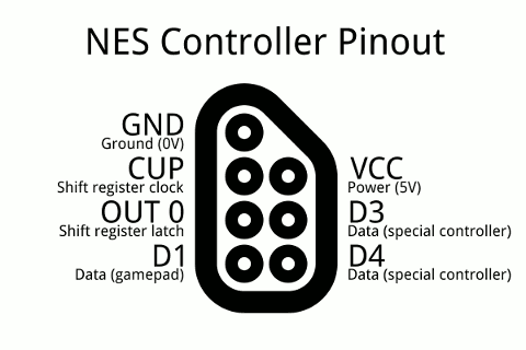
NES controller port(s) (if you want to use legacy NES controllers).
| Port 1 | Port 2 (optional) | Note | |
|---|---|---|---|
| GND | GND (- on board) | ||
| VCC (Power) | Connect to 3V3 | ||
| NES Clock | GPIO14 | GPIO1 | |
| NES LATCH | GPIO16 | GPIO20 | |
| NES Data | GPIO15 | GPIO21 |
Note
Soldering is required. There is only one 3v3 pin header on the board, the other 3V3 must be soldered directly onto pin 36 (3V3 OUT) of the Pico. For GND there are two pin headers available on the board. Clock Data and Latch for NES controller port 1 must be soldered directly onto the Pico. The Clock, Data and Latch for NES controller port 2 can be soldered on the available pin headers on the board, no need to solder them directly onto the Pico.

setting up the hardware
- Disconnect the Pico from your computer.
- Attach the Pico to the DV Demo Base.
- Connect the HDMI cable to the Demo base and your monitor.
- Connect the usb OTG cable to the Pico's usb port.
- Depending which controller you want to use:
- Connect the controller to the other end of the usb OTG.
- Connect legacy NES controller(s) to NES controller port(s).
- Insert the SD card into the SD card slot.
- Connect the usb power adapter to the usb port of the Demo base. (USB POWER)
- Power on the monitor and the Pico
Image: Usb controller only
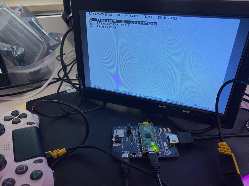
Image: one or two player setup with usb controller and NES controller port 2
In this image the NES controller port is wired to port 2.
For single player games: use USB controller.
For two player games: Connect a USB controller for player 1 and a NES controller for player 2 or connect a USB hub with two USB gamepads.
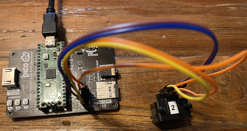
Image: Two player setup using two NES controllers or a USB controller and a NES controller
Controller port 1 pins must be soldered directly onto the Pico.
Controller port 2 pins can be soldered to the available headers of the Pimoroni DV.
For two player games:
- Connect two NES controllers or
- Connect a USB controller for player 1 and a NES controller for player 2. You can use either NES controller ports.
NOIMAGE - TODO
Raspberry Pi Pico or Pico 2, setup with Adafruit hardware and breadboard
Note
Instead of a Raspberry Pi Pico, you can also use a Pimoroni Pico Plus 2
materials needed
- Raspberry Pi Pico or Pico 2 with soldered male headers.
- Adafruit DVI Breakout For HDMI Source Devices
- Adafruit Micro-SD breakout board+
- Micro usb to OTG Y-Cable
- Breadboard
- Breadboard jumper wires
- Controllers (Depending on what you have)
- one or two NES controllers.
- Dual Shock 4 or Dual Sense Controller.
- HDMI Cable.
- Micro usb power adapter.
- Usb C to usb cable when using the Sony Dual Sense controller.
- Micro usb to usb cable when using a Dual Shock 4.
- FAT32 or exFAT formatted Micro SD card with roms you legally own. Roms must have the .nes extension. You can organize your roms into different folders.
flashing the Pico
- When using a Pico / Pico W, download piconesPlus_AdafruitDVISD_pico_arm.uf2 / piconesPlus_AdafruitDVISD_pico_w_arm.uf2 from the releases page.
- When using a Pico 2 or Pico 2 W, download piconesPlus_AdafruitDVISD_pico2_arm.uf2 / piconesPlus_AdafruitDVISD_pico2_w_arm.uf2 from the releases page.
- Push and hold the BOOTSEL button on the Pico, then connect to your computer using a micro usb cable. Release BOOTSEL once the drive RPI-RP2 appears on your computer. Or when already powered-on. Press and hold BOOTSEL, then press RUN on the board.
- Drag and drop the UF2 file on to the RPI-RP2 drive. The Raspberry Pi Pico will reboot and will now run the emulator.
Pinout
See https://www.raspberrypi.com/documentation/microcontrollers/images/pico-pinout.svg for the pinout schema of the Raspberry Pi Pico.
Use the breadboard to connect all together:
- Wire Pico Pin 38 to the breadboard ground column (-)
- Wire the breadboard left ground column (-) with the breadboard right ground column (-)
Adafruit Micro-SD breakout board+
| Breakout | GPIO | Note |
|---|---|---|
| CS | GPIO5 | |
| CLK (SCK) | GPIO2 | |
| DI (MOSI) | GPIO3 | |
| DO (MISO) | GPIO4 | |
| 3V | Pin 36 (3v3 OUT) | |
| GND | Ground on breadboard (-) |
Adafruit DVI Breakout For HDMI Source Devices
| Breakout | GPIO | Note |
|---|---|---|
| D0+ | GPIO12 | |
| D0- | GPIO13 | |
| CK+ | GPIO14 | |
| CK- | GPIO15 | |
| D2+ | GPIO16 | |
| D2- | GPIO17 | |
| D1+ | GPIO18 | |
| D1- | GPIO19 | |
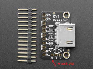
| 5 (*) | VBUS | Pin 40 (5volt) |
| GND (3x) | Ground on breadboard (-) |
(*) This is the via on the side of the board marked 5. (next to via D and C).
NES controller port(s). (if you want to use legacy NES controllers).
| Port1 | Port 2 (optional) | Note | |
|---|---|---|---|
| GND | |||
| VCC (Power) | (3v3 OUT) | ||
| NES Clock | GPIO6 | GPIO9 | |
| NES LATCH | GPIO8 | GPIO11 | |
| NES Data | GPIO7 | GPIO10 |
setting up the hardware
- Disconnect the Pico from your computer.
- Attach the Pico to the breadboard.
- Insert the SD card into the SD card slot.
- Connect the HDMI cable to the Adafruit HDMI Breakout board and to your monitor.
- Connect the usb OTG Y-cable to the Pico's usb port.
- Connect the Micro usb power adapter to the female Micro usb connecter of the OTG Y-Cable.
- Controllers (Depending on what you have)
- Connect the USB-controller to the full size female usb port of the OTG Y-Cable.
- Connect your NES controller(s) to the NES controller port(s).
- Power on the monitor and the Pico
See image below.
Note
The Shotky Diode (VSYS - Pin 39 to breadboard + column) and the wire on breadboard left (+) to right (+) are not necessary, but recommended when powering the Pico from a Raspberry Pi. See Chapter 4.6 - Powering the Board of the Raspberry Pi Pico Getting Started guide
Image: one or two player setup with usb controller and NES controller port
In this image the NES controller port is wired to port 1.
For single player games, connect either an USB controller or a NES controller. Not both!
For two player games: Connect a USB controller for player 1 and a NES controller for player 2.
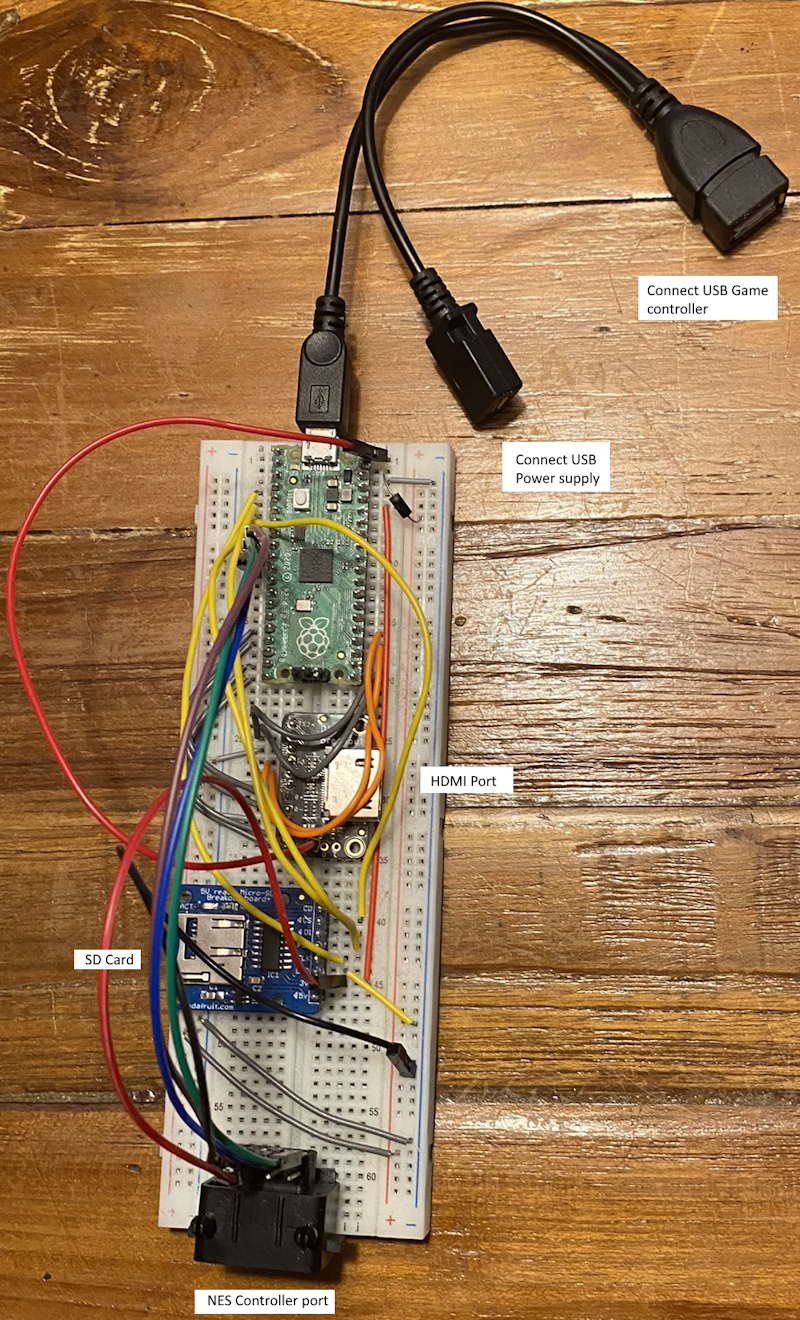
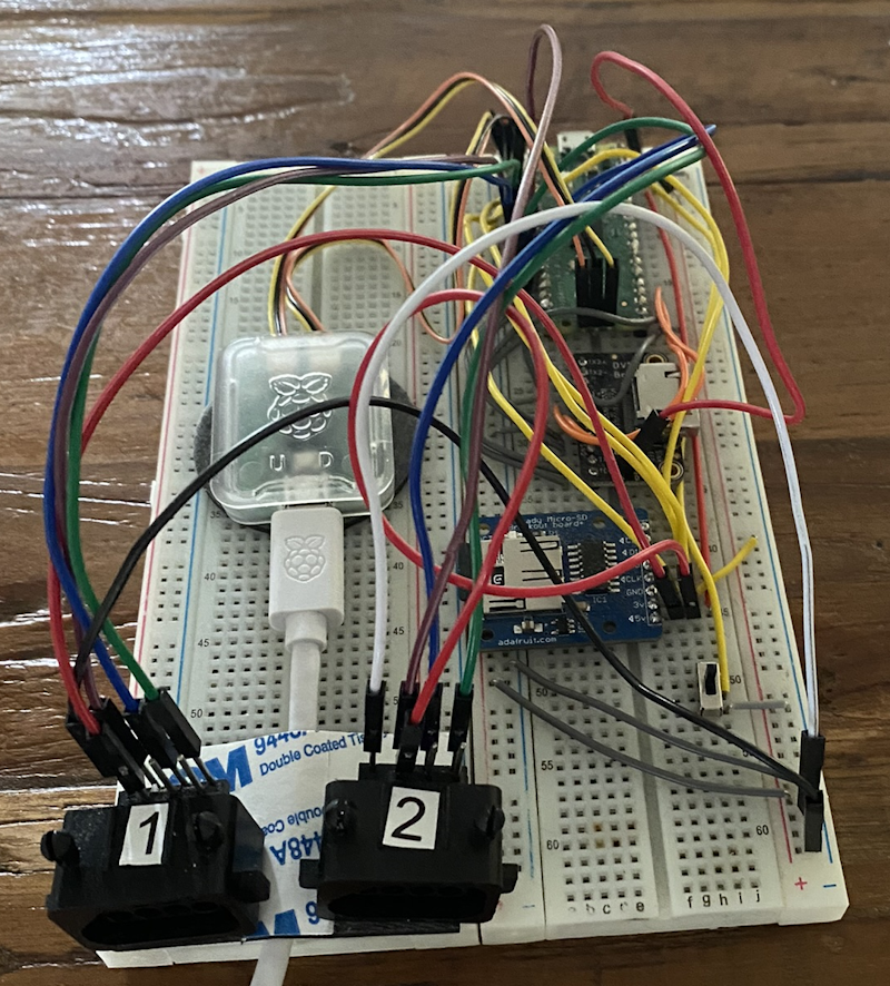
Image: Two player setup using two NES controllers or a USB controller and a NES controller
Choose either of the following:
- Connect two NES controllers
- Connect a USB controller for player 1 and a NES controller for player 2. You can use either NES controller ports.
Note
The device on the left is a Pico Debug probe used for debugging. This is optional
Adafruit Feather RP2040 with DVI (HDMI) Output Port setup
materials needed
- Adafruit Feather RP2040 with DVI (HDMI) Output Port
- SD Reader (Choose one below)
- Adafruit Micro-SD breakout board+ together with a breadboard.
- FeatherWing - RTC + SD - not tested by me, but should work.
- Breadboard
- Breadboard jumper wires
- USB-C to USB data cable.
- HDMI Cable.
- FAT32 or exFAT formatted Micro SD card with roms you legally own. Roms must have the .nes extension. You can organise your roms into different folders.
- Optional: a push button like this.
When using a USB gamecontroller this is needed:
- USB C male to micro USB female cable
- Micro usb to OTG Y-Cable
- Micro usb power adapter
- Usb C to usb cable when using the Sony Dual Sense controller.
- Micro usb to usb cable when using a Dual Shock 4.
When using legacy controllers, this is needed:
- USB-C Power supply
- Depending on what you have:
- one or two NES Controllers.
- WII-Classic controller
Pinout
See: https://learn.adafruit.com/assets/119662 for the Feather pin scheme.
Use the breadboard to connect all together:
- Wire the 3.3V Pin to the breadboard + column.
- Wire the GND Pin to the breadboard - column
- Wire the breadboard left ground column (-) with the breadboard right ground column (-)
- Optional: Attach a push button to the breadboard and connect a wire from this button to the Feather RST pin and breadboard ground column(-). This adds an extra easy to access Reset button.
Adafruit Micro-SD breakout board+
| Breakout | GPIO | |
|---|---|---|
| CS | GPIO10 | |
| CLK (SCK) | GPIO14 | |
| DI (MOSI) | GPIO15 | |
| DO (MISO) | GPIO8 | |
| 5V | USB | pin labelled USB on feather |
| 3V | See Note below | |
| GND | - column on breadboard connected to feather ground pin |
Note
The Adafruit Micro-SD breakout board+ has also a 3V input pin which can be connected to + column on breadboard connected to feather 3.3V pin. However, this gave me frequently errors trying to mount the SD card. So use 5V in stead.
WII nunchuck breakout adapter.
Connect the nunchuck breakout adapter to the Feather DVI using the STEMMA QT cable.
NES controller port(s). (if you want to use legacy NES controllers).
| Port 1 | Port 2 (optional) | Note | |
|---|---|---|---|
| GND | - column on breadboard connected to feather ground pin | ||
| VCC (Power) | + column on breadboard connected to feather 3.3V pin | ||
| NES Clock | GPIO5 | GPIO26 | |
| NES LATCH | GPIO9 | GPIO27 | |
| NES Data | GPIO6 | GPIO28 |
flashing the Feather RP2040
- Download piconesPlus_FeatherDVI_arm.uf2 from the releases page.
- Connect the feather to a USB port on your computer using the USB-C data cable.
- On the feather, push and hold the BOOTSEL button, then press RESET. Release the buttons, the drive RPI-RP2 should appear on your computer.
- Drag and drop the UF2 file on to the RPI-RP2 drive. The Raspberry Pi Pico will reboot and will now run the emulator.
Note
When the emulator won't start after flashing or powering on, and the screen shows 'No signal,' press the reset button once again. The emulator should now boot.
setting up the hardware
- Disconnect the Pico from your computer.
- Attach the Adafruit Feather RP2040 DVI to the breadboard.
- Insert the SD card into the SD card slot.
- Connect the HDMI cable to the HDMI port of the Adafruit Feather and to your monitor.
- Connect controllers depending on your setup:
- Legacy controllers.
- NES Controller to the NES controller port.
- WII-Classic controller to the Nunchuck Breakout Adapter.
- Connect USB-C power supply to USB-C connector.
- USB game Controllers
- Connect the USB C connector of the "male USB C to female micro usb cable" to the USB C port of the feather.
- Connect the female micro USB port of the "male USB C to female micro usb cable" to the male micro USB port of the USB OTG Y cable.
- Connect the Dual Sense or Dual Shock controller with the appropriate cable to the full size female usb port of the OTG Y-Cable.
- Connect the Micro usb power adapter to the female Micro usb connecter of the OTG Y-Cable.
- Legacy controllers.
- Power on the monitor and the Pico
Image: one or two player setup with usb controller and NES/WII_classic controller port
In this image the NES controller port is wired to port 1.
For single player games, connect either an USB controller or a NES/WII-classic controller. Not both!
For two player games: Connect a USB controller for player 1 and a NES or WII-Classic controller for player 2.
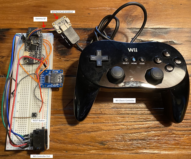
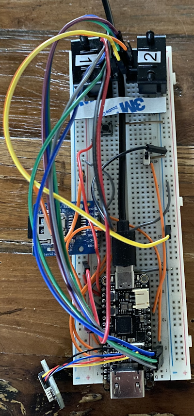
Image: Two player setup using two NES controllers or a USB controller and a NES/WII-classic controller
Choose either of the following:
- Connect two NES controllers
- Connect a WII-Classic Controller for player 1 and a NES-Controller on port 2 for player 2
- Connect a USB controller for player 1 and a NES controller for player 2. You can use either NES controller ports. You can also use the WII-classic controller for player 2.
Adafruit Metro RP2350
This configuration supports USB-Controller and legacy controllers. (NES / WII-classic).
Materials needed
- Adafruit Metro RP2350 or Adafruit Metro RP2350 with PSRAM
- 22-pin 0.5mm pitch FPC flex cable for DSI CSI or HSTX.
- Adafruit RP2350 22-pin FPC HSTX to DVI Adapter for HDMI Displays.
- USB-C power supply.
- USB-C to USB-C - USB-A Y cable. when using a USB game controller. The Y-cable is needed to connect the game controller and power the board at the same time.
- USB-C to USB-A cable for flashing the uf2 onto the board
- FAT32 or exFAT formatted Micro SD card with roms you legally own. Roms must have the .nes extension. You can organise your roms into different folders.
Note
Use an USB-c power supply to power the board instead of the barrel jack. Powering the board using the barrel jack can cause usb game controllers to not work properly.
Note
You can use the USB host pins on the board to connect a usb game-controller instead. Soldering is required for this. You also need to build the binary from source, since it is currently not included in the latest release. For more info see pio_usb.md
Legacy Controllers
- Depending on what you have:
- one or two NES Controllers.
- WII-Classic controller
WII nunchuck breakout adapter.
Connect the nunchuck breakout adapter to the Metro using the STEMMA QT cable.
NES controller port(s). (if you want to use legacy NES controllers).
| Port 1 | Port 2 (optional) | Note | |
|---|---|---|---|
| GND | Any GND pin | ||
| VCC (Power) | Any 3V3 pin | ||
| NES Clock | GPIO2 | GPIO5 | |
| NES LATCH | GPIO4 | GPIO7 | |
| NES Data | GPIO3 | GPIO6 |
flashing the Adafruit Metro RP2350
- Download piconesPlus_AdafruitMetroRP2350_arm.uf2 from the releases page.
- Connect the USB-C port to a USB port on your computer using the USB-C to USB-A data cable.
- On the board, push and hold the BOOT button, then press RESET. Release the buttons, the drive RPI-RP2 should appear on your computer.
- Drag and drop the UF2 file on to the RPI-RP2 drive. The board will reboot and will now run the emulator.
Adafruit Fruit Jam
Note
The latest HSTX video driver update adds support for HDMI audio output. Make sure External Audio is disabled in the options menu.
The new Adafruit Fruit Jam is supported as well.
materials needed
- Adafruit Fruit Jam
- USB gamepad
- Power to USB-C
- Optional
- If you want to use a WII-Classic controller:
- External speakers
Setup
- Connect your USB gamepad to the USB 1 port of the Fruit Jam.
- If you want to use a WII-Classic controller, connect the nunchuck breakout adapter to the Fruit Jam using the STEMMA QT cable and the Wii Classic controller to the breakout adapter.
- Connect external speakers to the audio output of the Fruit Jam.
To enable audio over HDMI make sure the setting External audio is disabled in the options menu.
When External audio is enabled, audio will be played through the external speakers and mini speaker simultaneously. Press Button 1 on the Fruit Jam to mute the mini speaker
Flash the firmware onto the Fruit Jam. (Connect Fruit Jam via his USB-C connector to computer, then Hold Reset and Button 1). Copy piconesPlus_AdafruitFruitJam_arm_piousb.uf2 to the RPI-RP2 drive.
Please keep the following in mind:
- Not all USB controllers from the supported controllers list are guaranteed to work.
- Two player mode is only possible with one USB gamepad on USB1 and one WII-Classic controller. USB2 is not supported for two player mode yet, will be looking into it.
- When an USB controller is connected, the WII-classic controller is player 2. To use the WII-Classic as player 1, unplug the USB controller.

Waveshare RP2040/RP2350-PiZero Development Board
materials needed
- One of these Waveshare boards:
- Waveshare RP2040-PiZero Development Board.
- Waveshare RP2350-PiZero Development Board.
- Optional: PSRAM chip When installed, the emulator loads ROMs from PSRAM instead of flash memory for significantly faster performance. Fully functional even without PSRAM. There is an issue with boards usings flash chips from another brand than Winbond, where the PSRAM is not working. See #191
- USB-C to USB-A cable for flashing the uf2 onto the board.
- USB-C Power supply. Connect to the port labelled USB, not PIO-USB. See note below.
- Mini HDMI to HDMI Cable.
- FAT32 or exFAT formatted Micro SD card with roms you legally own. Roms must have the .nes extension. You can organise your roms into different folders.
Additional for the RP2040-Pizero only:
- USB-C to USB-C - USB-A Y cable. when using an USB controller. Not needed for the Waveshare RP2350-PiZero where the controller must be connected to the PIO-USB port.
Note
Unlike the WaveShare RP2350-PiZero, where the controller must be connected to the PIO-USB port, the WaveShare RP2040-PiZero Development Board cannot use the PIO-USB port for the controller due to memory limitations. Instead, connect both the controller and the power adapter to the Y-cable, and then plug the Y-cable into the board’s port labeled “USB.” While the PIO-USB port can still be used to power the RP2040 board, I do not recommend this, as it has occasionally caused unstable behavior.
NES controller port.
When using a original NES controller you need:
For two player games with two NES controllers you need an extra NES controller port, controller and wire
| Port 1 | Port 2 (Optional) | Note | |
|---|---|---|---|
| GND | Any ground pin | ||
| VCC (Power) | 5Volt pin | ||
| NES Clock | GPIO5 | GPIO10 | |
| NES LATCH | GPIO9 | GPIO11 | |
| NES Data | GPIO6 | GPIO12 |
Note
Contrary to other configurations where VCC is connected to 3Volt, VCC should be connected to a 5Volt pin. Otherwise the NES controller could possibly not work.
WII-Classic controller.
When using a WII-Classic controller you need:
- Adafruit Wii Nunchuck Breakout Adapter - Qwiic / STEMMA QT
- STEMMA QT / Qwiic JST SH 4-pin Cable with Premium Female Sockets
- WII Classic wired controller
Connections are as follows:
| Nunchuck Breakout Adapter | RP2040-PiZero |
|---|---|
| 3.3V | 3V3 |
| GND | GND |
| SDA | GPIO2 |
| SCL | GPIO3 |
flashing the Waveshare RP2040-PiZero Development Board
- Download piconesPlus_WaveShareRP2040PiZero_arm.uf2 from the releases page.
- Connect the USB-C port marked USB (not PIO-USB) to a USB port on your computer using the USB-C to USB-A data cable.
- On the board, push and hold the BOOT button, then press RUN. Release the buttons, the drive RPI-RP2 should appear on your computer.
- Drag and drop the UF2 file on to the RPI-RP2 drive. The board will reboot and will now run the emulator.
flashing the Waveshare RP2350-PiZero Development Board
- Download piconesPlus_WaveShareRP2350PiZero_arm_piousb.uf2 | Readme from the releases page.
- Connect the USB-C port marked USB (not PIO-USB) to a USB port on your computer using the USB-C to USB-A data cable.
- On the board, push and hold the BOOT button, then press RUN. Release the buttons, the drive RPI-RP2 should appear on your computer.
- Drag and drop the UF2 file on to the RPI-RP2 drive. The board will reboot and will now run the emulator.
Note
When the emulator won't start after flashing or powering on, and the screen shows 'No signal,' press the run button once again. The emulator should now boot.
Image: one or two player setup with usb controller and NES controller port
In this image the NES controller port is wired to port 1.
For single player games, connect either an USB controller or a NES controller. Not both!
For two player games: Connect a USB controller for player 1 and a NES controller for player 2.
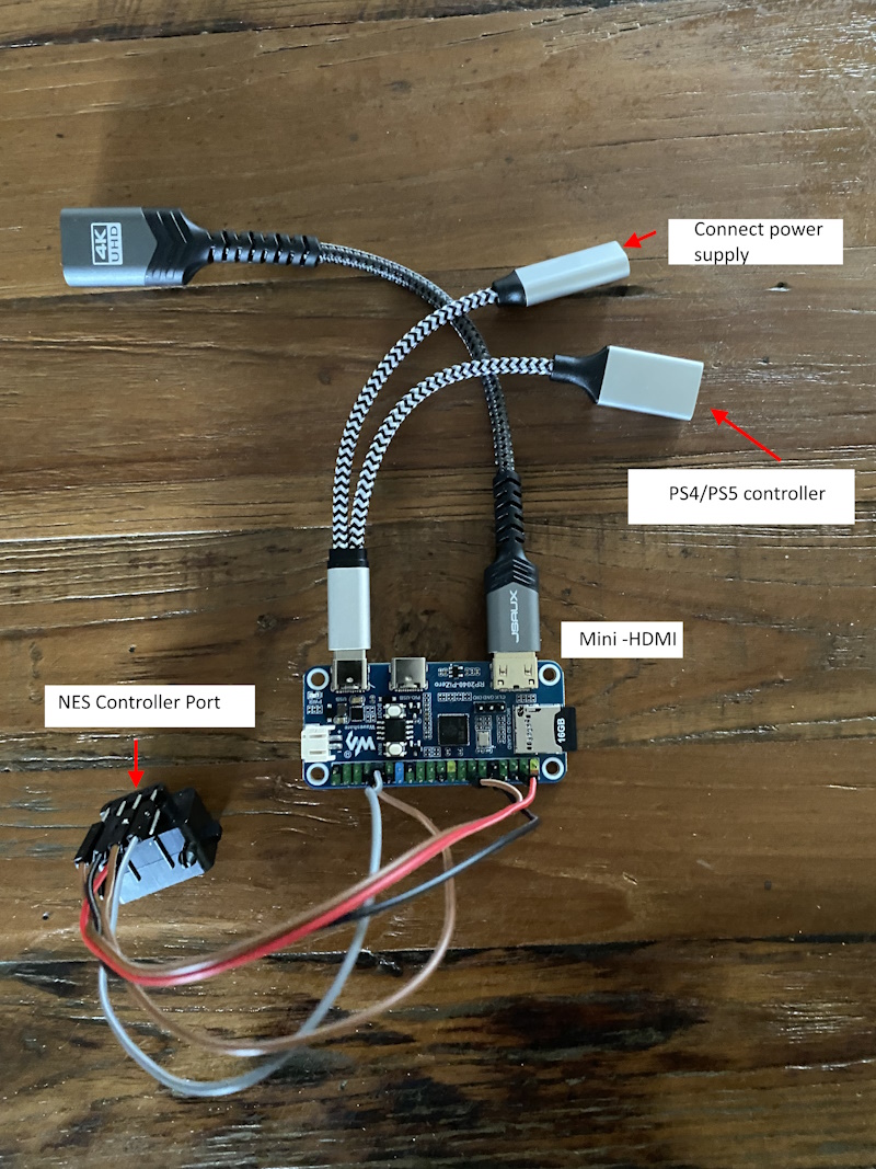
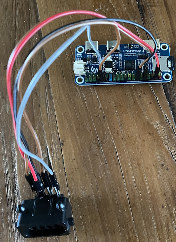
Image: Two player setup using two NES controllers or a USB controller and a NES controller
Choose either of the following:
- Connect two NES controllers
- Connect a USB controller for player 1 and a NES controller for player 2. You can use either NES controller ports.
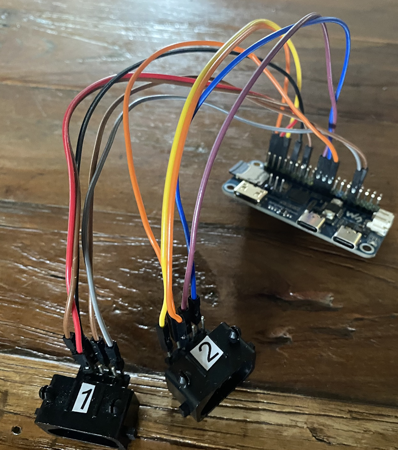
Image: Using a wii-classic controller


3D printed case for RP2040/RP2350-PiZero
Gavin Knight (DynaMight1124) designed a NES-like case you can 3d-print as an enclosure for this board. This enclosure is designed for 2 NES controller ports so you can play 1 or 2-player games. Click here for the design. Please contact the creator on his Thingiverse page if you have any questions about this case.


PCB with Raspberry Pi Pico or Pico 2
Create your own Pico-based NES console. It features two NES controller ports for 1 or 2-player games.
Designed by @johnedgarpark

Several Companies can make these PCBs for you.
I personally recommend PCBWay. The boards i ordered from them are of excellent quality. They have also a very short lead time. Boards i ordered on Monday arrived from China to my home in the Netherlands on Friday of the same week.

When ordering, simply upload the zip file containing the gerber design. This file (pico_nesPCB_v2.1.zip) is available in the releases page and can also be found in the PCB folder.
Note
Soldering skills are required. Make sure you solder all the connections from the Pico onto the PCB. Also the connections on the short right-side of the Pico. (For ground)
Note
If you are looking for the previous design (v0.2). You can find it here
Note
Sellers on AliExpress have copied the PCB design and are selling pre-populated PCB's. For questions about those boards, please contact the seller on AliExpress.
Other materials needed:
- Raspberry Pi Pico or Pico 2 with no headers.
- Adafruit DVI Breakout Board - For HDMI Source Devices
- Adafruit Micro SD SPI or SDIO Card Breakout Board - 3V ONLY!
- For the NES Controllers:
- Micro usb to OTG Y-Cable if you want to use a Dualshock/Dualsense controller.
- Micro USB power supply.
- Optional: on/off switch, like this
When using a Pico / Pico W, Flash piconesPlus_AdafruitDVISD_pico_arm.uf2 / piconesPlus_AdafruitDVISD_pico_w_arm.uf2 from the releases page. When using a Pico 2 or Pico 2 W, flash piconesPlus_AdafruitDVISD_pico2_arm.uf2 / piconesPlus_AdafruitDVISD_pico2_w_arm.uf2 instead.
Important
You cannot use a Pimoroni Pico Plus 2 because of the SP/CE connector on the back of the board.
Image: Two player setup using two NES controllers or a USB controller and a NES controller
Choose either of the following:
- Connect two NES controllers
- Connect a USB controller for player 1 and a NES controller for player 2. You can use either NES controller ports. Use the OTG Y-Cable to connect an USB power supply and the USB controller.

3D printed case for PCB
Gavin Knight (DynaMight1124) designed a NES-like case you can 3d-print as an enclosure for this pcb. You can find it here: https://www.thingiverse.com/thing:6689537. Here you can find two designs: the latest design for PCB v2.0 and the previous design for PCB v0.2. In the latest v2.0 design, you can choose between two top covers, one with a button connecting to the bootsel button for easy firmware upgrades, the other without the button. In this case you have to remove the top cover to access the bootsel button. See images below. Make sure to print the correct files for the PCB version you own. You can find more information on Gavin's Thingiverse page.
Top Cover v2.0 without button (Top_v2.0.stl)

Top Cover v2.0 with bootsel button (Top_v2.0_with_Bootsel_Button.stl)

Base v2.0 (Base_v2.0.stl)

on/off button (Power_Switch.stl)

PCB with WaveShare RP2040/RP2350 Zero
Create your own Pico-based NES console. It features two NES controller ports for 1 or 2-player games. This version is smaller than the above and uses cheaper, but ultimately harder to solder components. This is a more advanced project than the above PCB design, if you are unsure of your soldering capabilities I wouldnt recommend this PCB.
Several companies can make these PCBs for you. PCBWay or JLCPCB are two good options.
I personally recommend PCBWay. The boards I ordered from them are of excellent quality. They have also a very short lead time. Boards I ordered on Monday arrived from China to my home in the Netherlands on Friday of the same week.
When ordering, simply upload the zip file containing the gerber design. This file (Gerber_PicoNES_Mini_PCB_v2.0.zip) is available in the releases page and can also be found in the PCB folder.
Note
Soldering skills are required. Make sure you solder all the connections from the Pico onto the PCB. This version requires good soldering skills especially for the HDMI portion, a good amount of flux and a fine tip will be required, additional solder can be wicked away with solder wick. I recommend starting with the resistor arrays first, then the HDMI port, after that either Pico or MicroSD adaptor, lastly the NES Ports, which can be hard to push into the PCB.
Please see the Instrucables link for guide and components needed: https://www.instructables.com/PicoNES-RaspberryPi-Pico-Based-NES-Emulator/
When using a RP2040 Zero, Flash piconesPlus_WaveShareRP2040ZeroWithPCB_arm.uf2 from the releases page. When using a RP2350 Zero, flash piconesPlus_WaveShareRP2350PiZero_arm_piousb.uf2 instead.
3D printed case for PCB
Gavin Knight (DynaMight1124) designed a NES-like case you can 3D print as an enclosure for this PCB. You can find it here: https://www.thingiverse.com/thing:7041536. If you dont own a 3D printer, you can either find a local company that can offer 3D print services or use professional services such as PCBWay or JCLPCB, the professional services can offer extremely high quaility finishes.
3D printed case

3D printed case from professional services (JLCPCB in this example)


Soldered PCB

Note
The PCB has been updated to v2.0, with improvements to the SD slot and easier to solder components around the HDMI port, however you can still find v1.0 design files, gerber and BOM here: https://www.thingiverse.com/thing:7041536
PCB with WaveShare RP2350 USB A
Based around the WaveShare RP2350 USB A board along with a PCB, which creates a micro PicoNES with 1 player controls via USB. Theres a full guide here: https://www.instructables.com/PicoNES-RaspberryPi-Pico-Based-NES-Emulator/
Several companies can make these PCBs for you. PCBWay or JLCPCB are two good options.
I personally recommend PCBWay. The boards I ordered from them are of excellent quality. They have also a very short lead time. Boards I ordered on Monday arrived from China to my home in the Netherlands on Friday of the same week.
PicoNES Micro populated PCB - NES controller shown for scale

3D Printed Case

Build Guide
https://www.instructables.com/PicoNES-RaspberryPi-Pico-Based-NES-Emulator/
Note
Due to the small size, micro soldering skills are required. It uses 0603 sized SMD components. Please see the Instructables link for information.
Using metadata.
Download the metadata pack from the releases page and extract its contents to the root of the SD card. It contains box art and game info for many games. The metadata is used in the menu to show box art and game info when a rom is selected. Press START to view the information. When the screensaver is started, random box art is shown.

Gamepad and keyboard usage
| (S)NES | Genesis | XInput | Dual Shock/Sense | |
|---|---|---|---|---|
| Button1 | B | A | A | X |
| Button2 | A | B | B | Circle |
| Select | select | Mode or C | Select | Select |
Menu
Gamepad buttons:
- UP/DOWN: Next/previous item in the menu.
- LEFT/RIGHT: next/previous page.
- Button2: Open folder/flash and start game.
- Button1: Back to parent folder.
- START: Show metadata and box art (when available)
- SELECT: Opens a setting menu. Here you can change settings like screen mode, scanlines, framerate display, menu colors and other board specific settings. Settings can also be changed in-game by pressing some button combinations as explained below. The settings menu can also be opened in-game.
- SELECT + Button1: Force DVI mode (HSTX only). Useful if a DVI monitor shows no picture. This will restore the image. Enabling External audio also forces DVI mode.
When using an USB-Keyboard:
- Cursor keys: Up, Down, left, right
- Z: Back to parent folder
- X: Open Folder/flash and start a game
- S: Show metadata and box art (when available).
- A: acts as the select button.
Emulator (in game)
more like this
smb-vanilla-port
A C and C++ decompilation of the NES games "Super Mario Bros" and "Super Mario Bros: The Lost Levels"
RaspPi-Pico-Examples-Fedora
Compiling Raspberry Pi Pico RP2040 / Pico2 RP2350 C/C++ programs on Fedora