DIY-CNC-machine
How to build your own CNC machine from scratch
 maxvfischer
git clone https://github.com/maxvfischer/DIY-CNC-machine.gitmaxvfischer/DIY-CNC-machine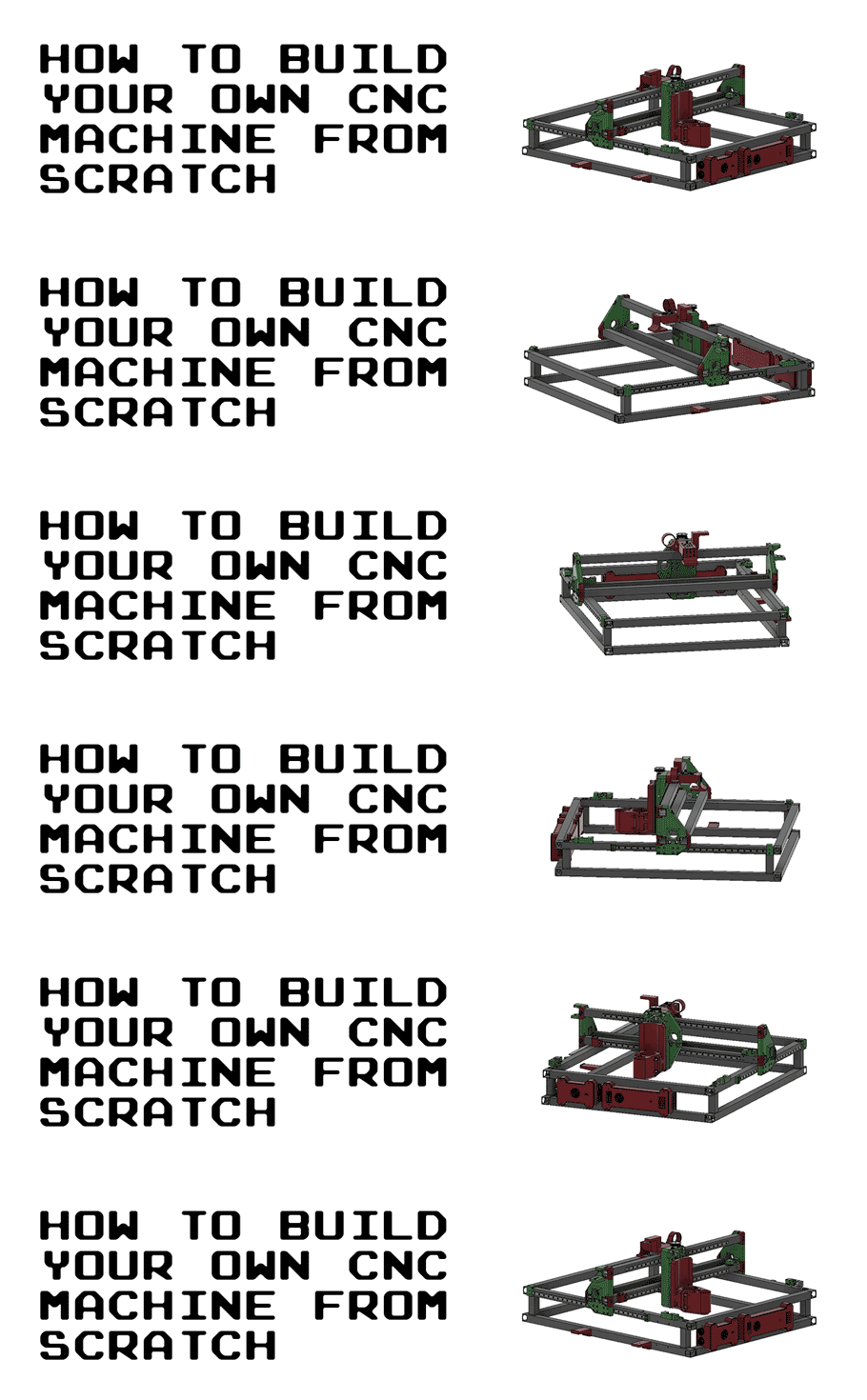
This guide goes through all the steps to build your own CNC machine from scratch. It includes a complete bill of materials (BOM), STL/OBJ-files for all the 3d-printed parts and detailed instructions of how everything is assembled. It also includes instructions of how all the necessary open-source softwares are installed.
The guide is based on Ivan Miranada's design and is a complement to Ivan's Youtube-videos:
- Original video: https://www.youtube.com/watch?v=_atw3e0nIrg
- Updates with geared stepper motors etc: https://www.youtube.com/watch?v=qpjf5D3WngY
- Updating to metal parts: https://www.youtube.com/watch?v=RDnGvhdGFEY
If you have any questions, feel free to contact me on LinkedIn: https://www.linkedin.com/in/max-fischer-92997281/
or

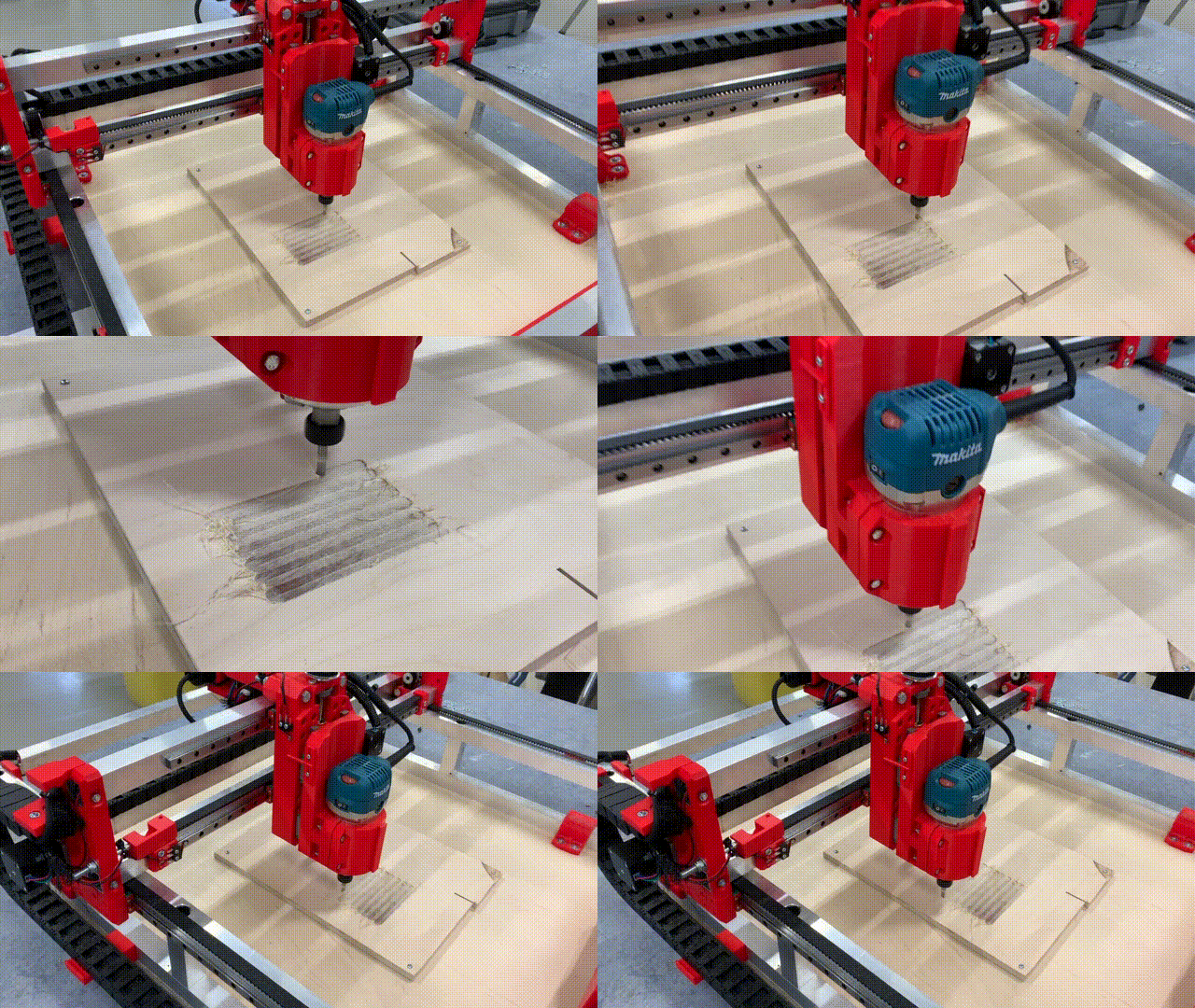
Featured on
- Hackernews (#2): https://news.ycombinator.com/item?id=29096954
- Console open-source newsletter: https://console.substack.com/p/console-83
- Hackaday's blog: https://hackaday.com/2021/11/05/diy-cnc-uses-lots-of-3d-printed-parts/
- Hackaday's podcast (~25:30): https://open.spotify.com/episode/2YuxrVAgbQvVTjcUljJ3rj?si=lkp1L061R7ix6WkA7s1ieA
- Arduino's official blog: https://blog.arduino.cc/2021/11/03/learn-how-to-build-your-own-massive-3d-printed-cnc-router/
- Weekly robotics newsletter: https://weeklyrobotics.com/weekly-robotics-168
Table of content
- License
- Parts (bill of materials)
- Build the CNC machine
- Main frame
- Y-axis
- X-axis and Z-axis
- Rails to bridge beams
- X-axis tensioner and end-stop mount to lower bridge beam
- Bridge beams to side plates
- Rod bearings to carriage
- Carriage to bridge beams
- X-axis motor, idlers and pulley to carriage
- X-axis HTD5M belt
- Acme nut and rails to carriage slider
- Acme rod and vertical slider to carriage
- Z motor mount and X-axis cable chain
- Y-axis cable chain
- Z stepper motor, pulleys and belt
- Stepper motors and end-stops
- Router
- Electronic boxes
- Electrical wiring and connect components
- Main power supply
- Prepare power to steppers and connect fans and LED
- Assemble stepper motor drivers and tune VRef
- Attach Arduino and solder USB cable
- Stepper and end-stop cable management to small electronic box
- Connect steppers to CNC shield
- Connect end-stops to CNC shield
- Set microstepping
- Router cable management and connect to main power supply
- Final test of electrical wiring
- Wasteboard
- Dust shoe (updated Feb 4, 2022)
- Software
- Final notes
License
The following license is included when buying Ivan Miranda's blueprints of the CNC machine:
Everything that is in these files that I produced myself, apart from reselling the files, is allowed.
You can print and sell parts, sell machines, sell courses to build the machine. Modify the parts and post
them for free, as long as you don’t sell the files and keep this license on everything you make with the
files and credit me, we’re good. No DRM or anything, you are even allowed to repost the files as long as
they’re kept free. Why buy this then? To support me and keep me encouraged to do more projects like this.
Ivan does an amazing job putting these DIY builds together. I've posted his STL-files in this repository to simplify the build, but PLEASE buy his blueprints here: https://ivanmiranda.com/products/3d-printed-cnc. It's only $25 and helps him to continue build and share his awesome projects. Also, you will get access to a Discord channel that is really useful, where you can ask questions to a lot of people who have already built the machine.
Also, the Z-axis end-stop trigger, the ordinary end-stops and the rail supports all come from cello4's GitHub: https://github.com/4cello/mirandacnc-community.
Parts (bill of materials)
CLICK HERE TO OPEN THE BILL OF MATERIALS (BOM) MARKDOWN: Bill of materials
To simplify the build, I've created a separate markdown page with tables covering all parts needed to build the CNC-machine. The tables include a unique Item No. to easier refer to the parts in the guide. The tables also include images of all parts and .STL/.OBJ files of the parts that needs to be 3d-printed.
To get an even better understanding of how all the parts are used, I've created a detailed spreadsheet with comments:
To be able to continue with the build, you need to buy and 3d-print all needed parts found in the bill of materials.
Build the CNC machine
This section covers how all the parts is put together to build the CNC machine.
All the measurements, distances and a complete overview of how everything comes together can be found in the main Fusion 360 CAD design. It can be downloaded here:
Please note that the main Fusion 360 design is quite messy, which is one of the reasons why I've extracted the needed parts in a separate bill of materials.
Fusion 360 is a CAD program developed by Autodesk. It's free for personal use and can be downloaded here: https://www.autodesk.com/products/fusion-360/personal. After you've downloaded Fusion 360, import fusion_360_cad_files.f3z to load the main CAD design. This can also come in handy if you need to adjust some of the 3d-printed parts.
Main frame
Drill holes in 900 mm profiles
The main frame consists of two separate frames, the lower and the upper frame. The two frames are kept together using threaded rods, washers and nuts. To enable the threaded rods to slide through the aluminium profiles, holes needed to be drilled.
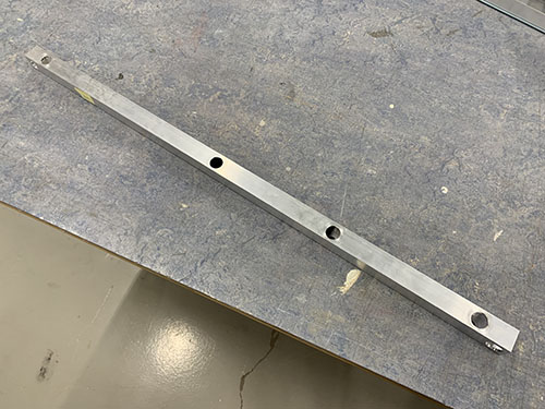
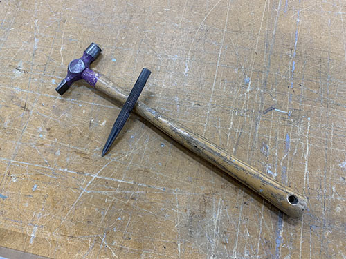
First, a sharpie was used to indicate where all the holes were going in the 900mm profiles (O07). This was done by using a set square and a penn. A bradawl and a hammer were then used to make indentations at the center of the holes.
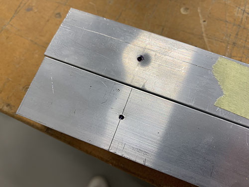
A 9 mm drill-bit and a bench drill was used to drill the holes straight through the profiles.
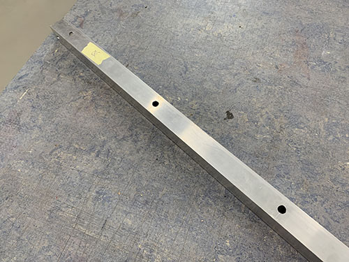
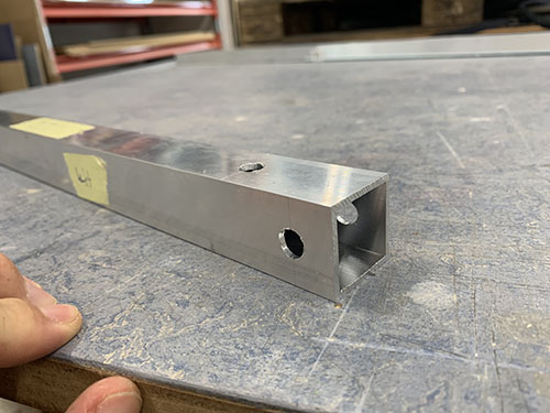
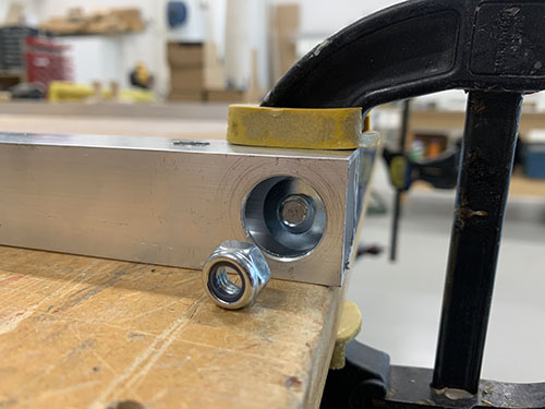
To be able to access the nuts and tight them with a socket wrench, some holes (facing outwards, see Fusion360 CAD file) needed to be enlarged. A sharpie was used to mark all the holes that needed to be enlarged.
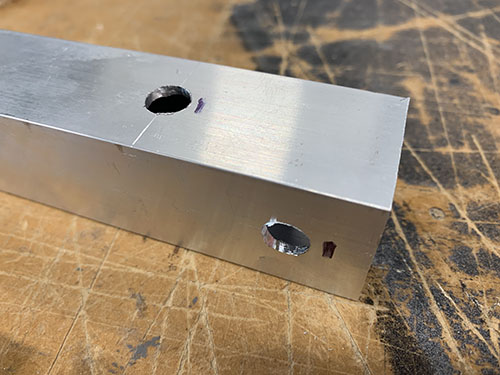
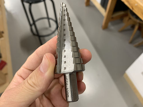
A step drill was then used to enlarge the holes holes to 20 mm. A tip is to measure the size of your socket wrench and keep the holes as small as possible, while you're still able to tighten the nuts. To be able to see which step you're aiming for on the step drill, attach a small piece of masking tape on the step above.
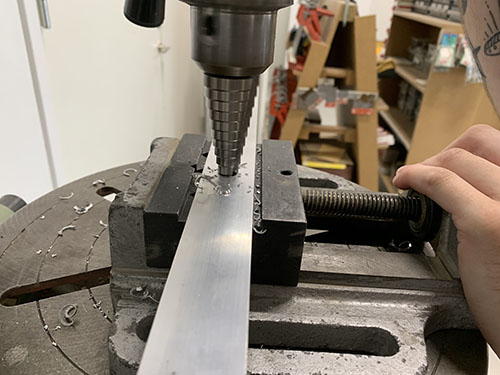
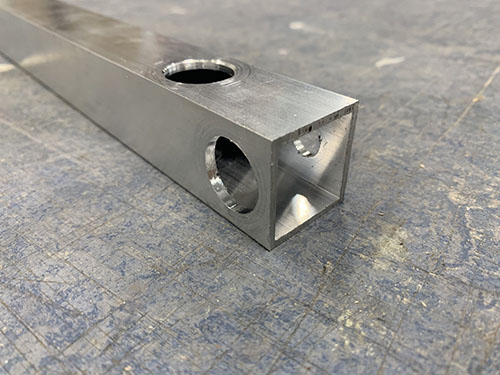
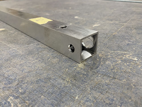
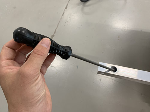
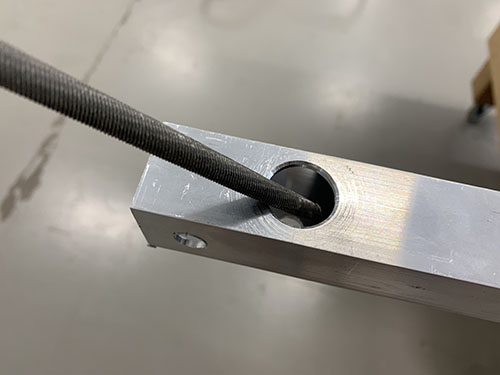
The edges were finally smoothed out using a round metal file.
Rails to 900 mm profiles
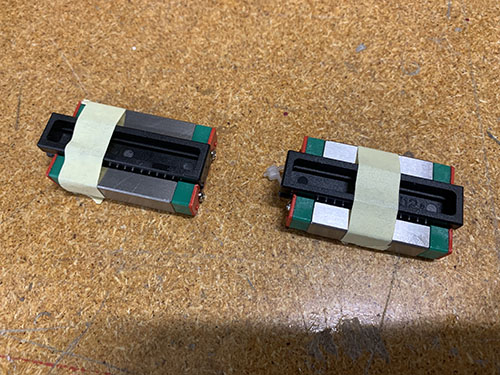
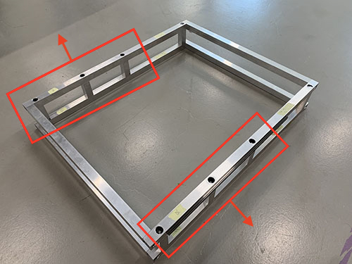
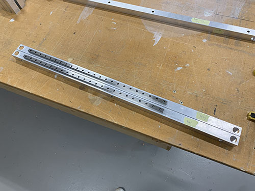
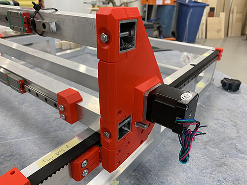
Before the upper and lower frames were assembled, two 600 mm MGN12H rails (O21) were attached to the 900 mm aluminium profiles (O07) of the upper frame. They were attached to the sides facing outwards and above the three 80 mm vertical beams (connecting the lower and upper frame). A tip is to place all the profiles as they should go to make sure that you're attaching the rails to the correct faces (see the red boxes on the image below). Also, be very careful when removing the MGN12H blocks (O22) from the rails.
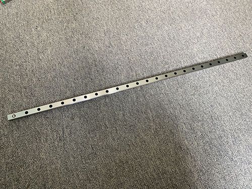
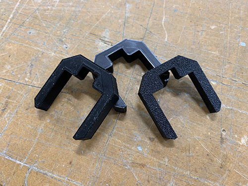
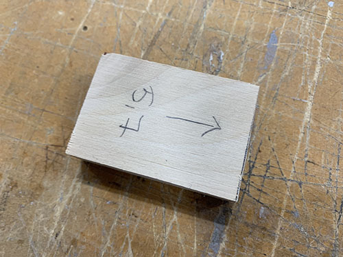
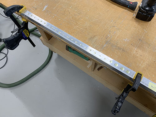
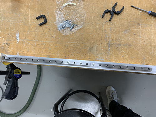
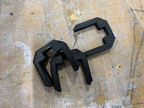
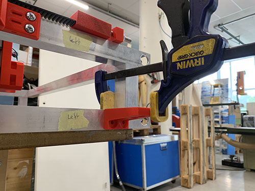
3x 3d-printed support tools (P25) were used to center the rails on the profiles. A 57 mm wood block were cut out and used to attach the rails at the same distance from the end of the profiles on both sides. The rails were then clamped to the profiles.
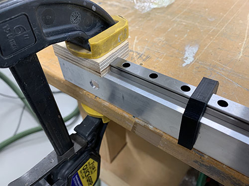
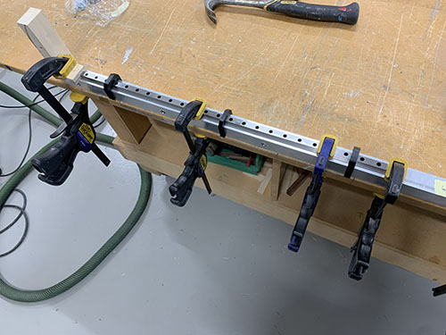
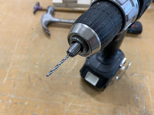
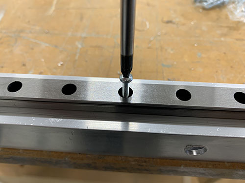
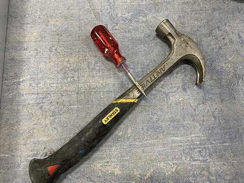
A bradawl and a hammer were then used to make indentations at the center of the holes. Cutting fluid was applied and a 2 mm drill was used to drill all the holes.
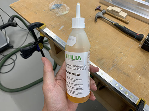
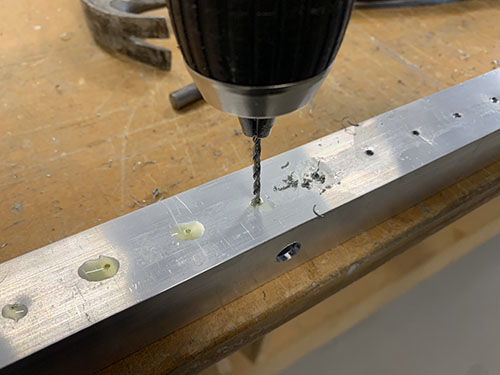
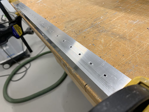
Cutting fluid was then applied once more on the drilled holes and a M3 drill tap was used to create threads in the holes.
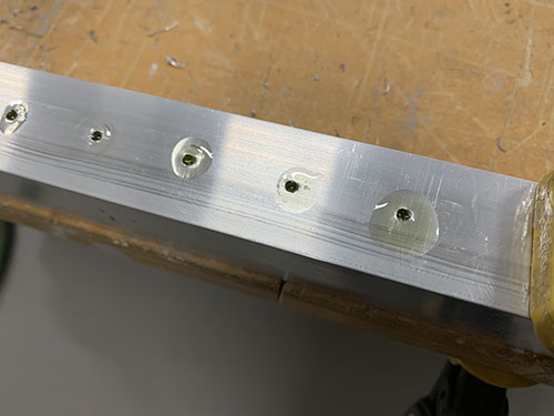
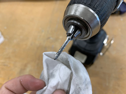
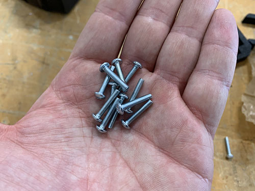
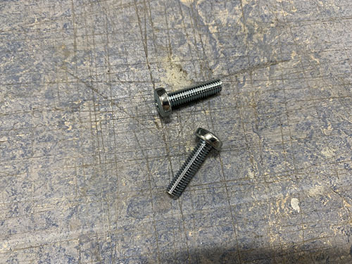
Finally, the rails were attached using 48x 16 mm M3 screws (S03).
Assemble upper and lower frames
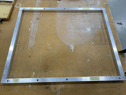
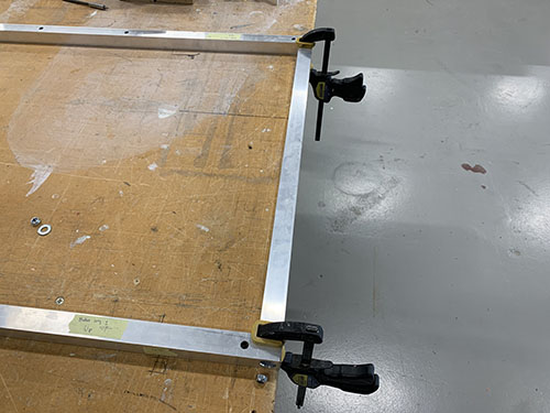
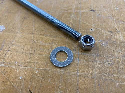
The two frames were assembled using the 4x 717 mm M8 threaded rods (T03), 8x (20mm, 10mm, 2mm) washers (W04) and 8x M8 lock nuts (N03).
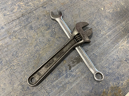
The profiles were first placed in their correct place and clamps were used to keep the profiles aligned. I used two jointed spanners (one one each side) to lock everything in place, but you can also use two socket wrenches. Just make sure that the bits fit into the drilled holes.
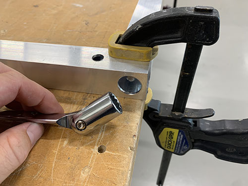
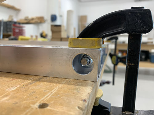
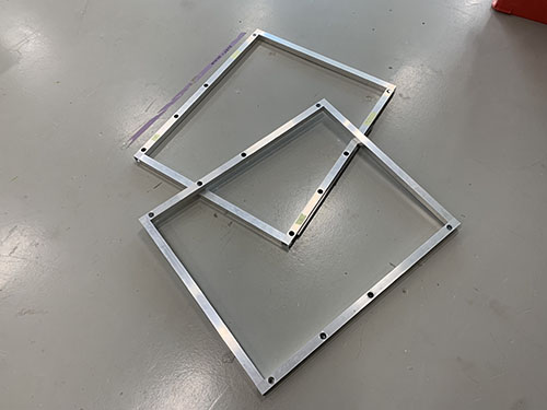
Interlock upper and lower frames
The upper and lower frames and the 8x 80 mm vertical aluminium beams (O06) were first layed out in their correct place. The 803 mm horizontal bridge beams (used later in the tutorial) (O05) and clamps were then used to align the frames on top of each other.
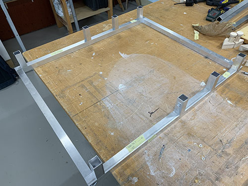
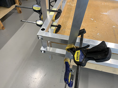
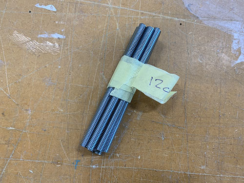
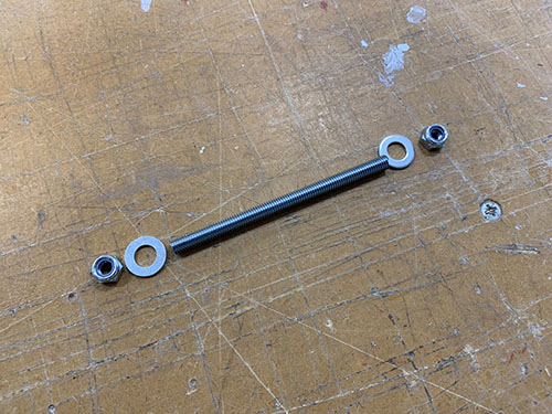
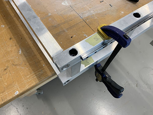
8x 120 mm M8 threaded rods (T02), 16x (20mm, 10mm, 2mm) washers (W04) and 16x M8 lock nuts (N03) were then used to interlock the upper and lower frames, with the 80 mm vertical aluminium profiles in between.
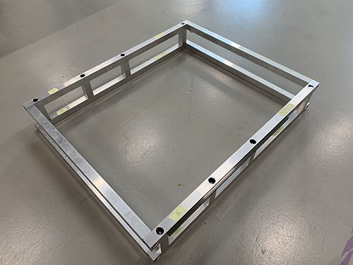
Y-axis
Side plates to upper frame
Before attaching the side plates, the MGN12H blocks (O22) were added back onto the rails, 2x on each side. Be careful when sliding them onto the rails, there are multiple small bearing balls that easily fall out of the blocks.
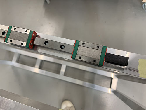
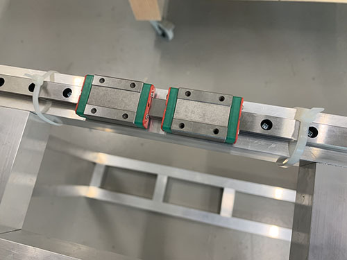
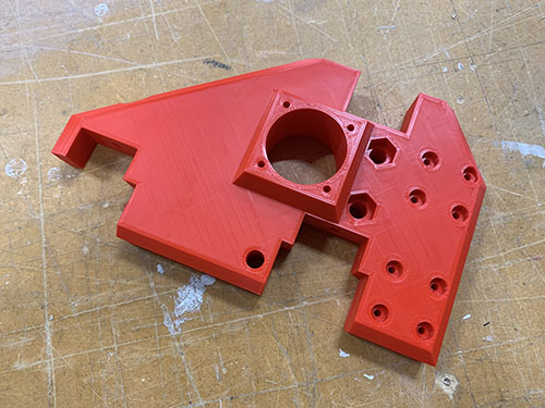
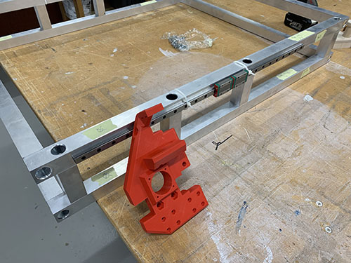
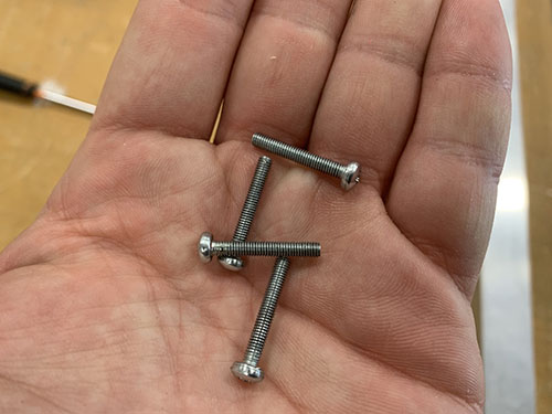
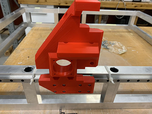
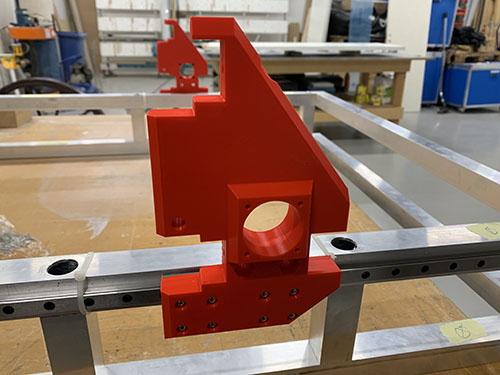
The left (P20) and right (P29) side plates where then attached to the blocks using 16x 20 mm M3 screws (S04) (8x on each side plate). Make sure to attach the plates on the correct side (see images below).
I had to redesign the left side plate and reprint it later in the build (after the images were taken). Therefore, the left side plate seen in the upcoming images look a bit different than the one used (see next image for the left side plate used).
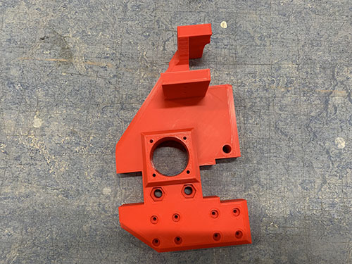
Y-axis motors, idlers and pulleys to side plates
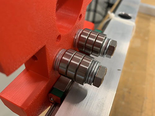
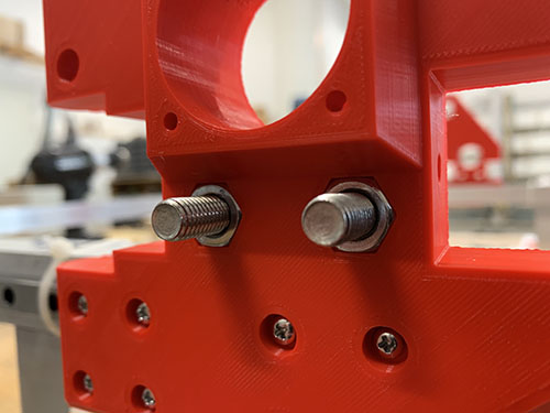
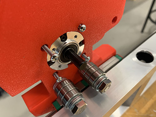
Each idler were made up out of 1x idler blocker (P16), 2x 60 mm fully threaded M8 screws (S15), 6x 698zz bearings (O01) and 8x (15 mm x 8.5 mm x 1.5mm) washers (W03) (2x closest to the idler blocker and 6x closest to the side plate). The idlers were then attached to each side plate using two M8 nuts (N03). Make sure that the bearings are spinning freely.
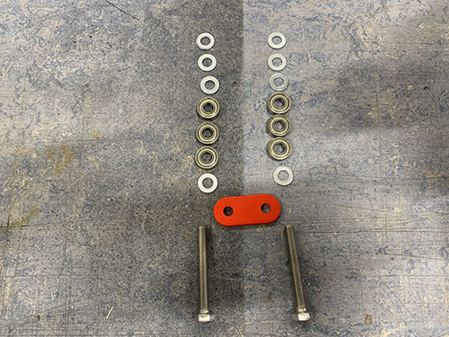
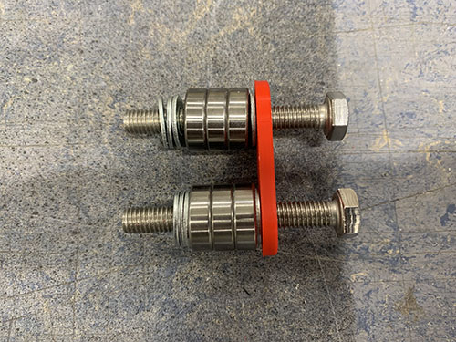
As I designed and added the idler blocker later on in the build, some of the images doesn't have it and they also have 3x washers instead of 1x washer closest to the screw head. I left these images anyways in the guide so you can see how it looks when you attach the idlers, but please ignore the wrong number of washers. Also ignore all the other things around the idlers in the upcoming 2 images, they are taken later on in the build.
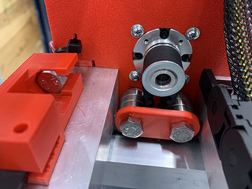
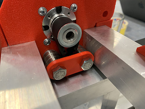
Should be idler blockers and a different number of washers in the upcoming images.
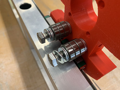
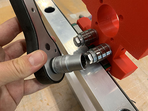
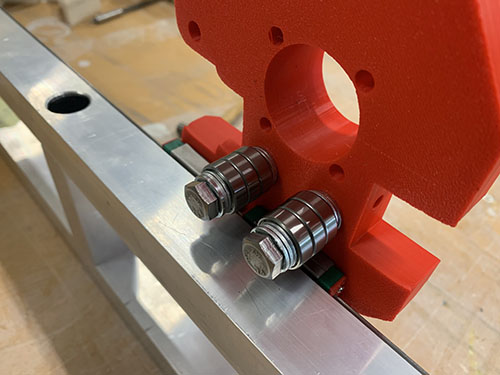
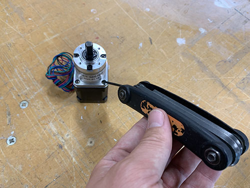
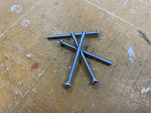
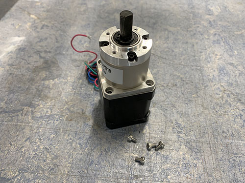
To attach the stepper motors to the side plates, the 4x M3 screws (S07) locking the gear box to the motor were removed. Save these as they will be used later on to attach the power supply and Arduino to the electronic boxes.
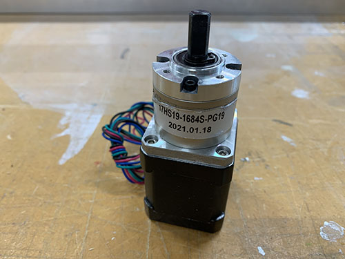
The 2x geared stepper motors (E18) were then inserted into the large holes on the side plates, facing inwards. 4x 40 mm M3 screws (S06) and 4x M3 washers (W05) were used to lock each stepper motor to the side plates (I forgot to add the washers in the images below, therefore they're not visible). The motors should be attached so that the cables are facing in the direction of the two bridge beams (i.e. the longer vertical surface on the side plates).
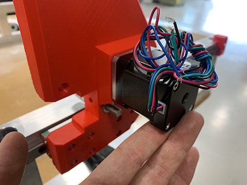
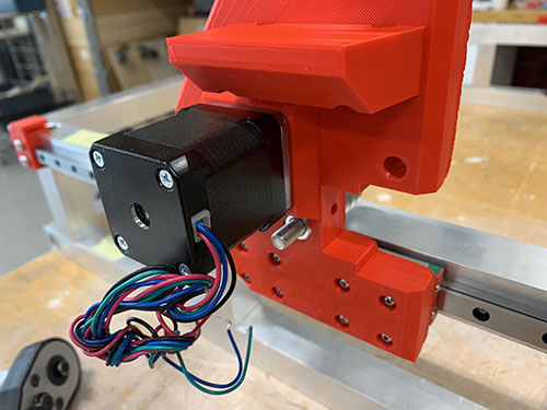
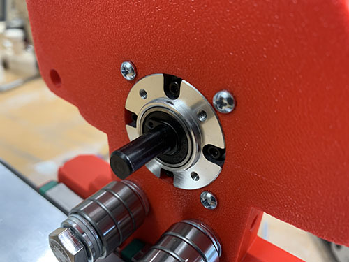
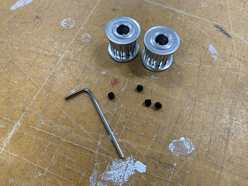
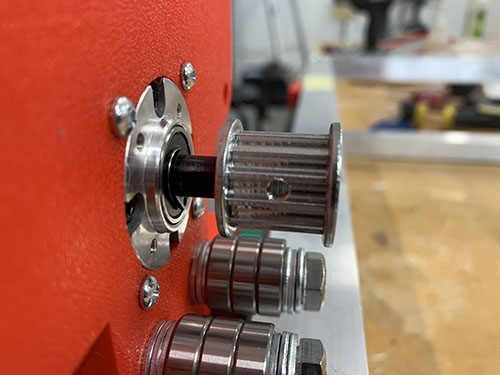
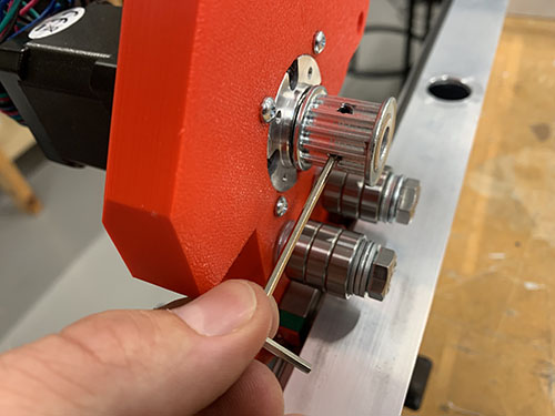
1x HTD5M timing pulley (O18) was attached to each motor shaft using set screws.
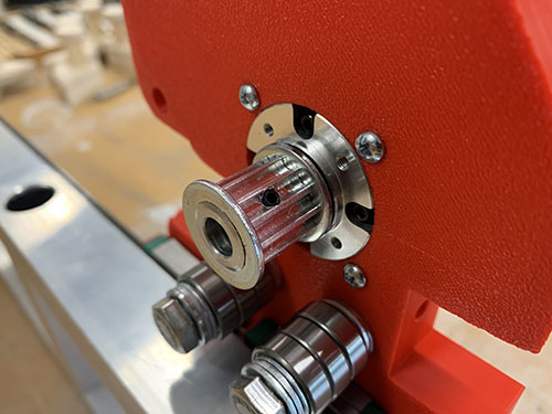
Y-axis belt tensioners and end-stop mounts
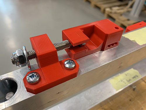
2x fixed belt tensioners (P19, P28) were attached to the longer aluminium profiles of the upper frame using 4x 20mm M5 screws (S12) (2x for each fixed belt tensioner). When aligning the fixed belt tensioners, make sure that the "belt opening" is pointing in the direction of the rails (1x fixed belt tensioner for each rail). Also make sure that the fixed belt tensioners are positioned on the correct side of the rail (see images). Similar to before, a bradawl and a hammer were used to make indentations at the center of the holes. Cutting fluid was applied and a 4 mm drill was used to drill the holes, followed by a M5 drill tap.
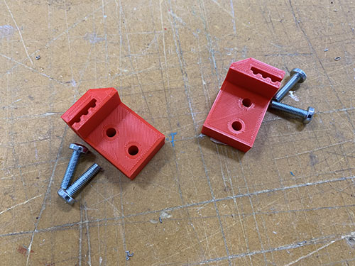
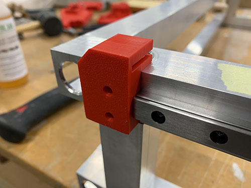
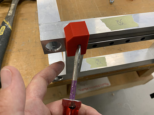
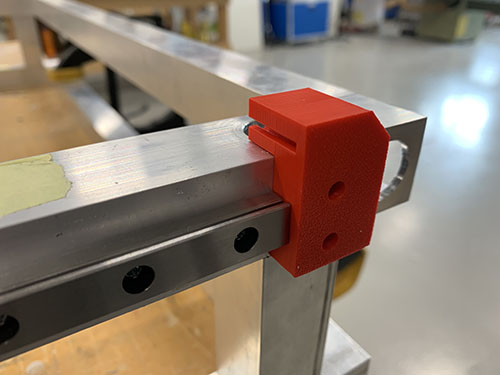
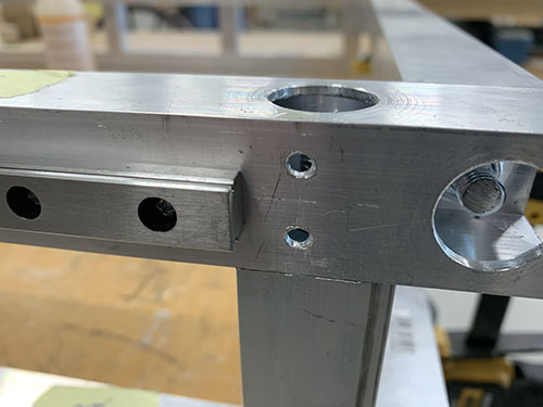
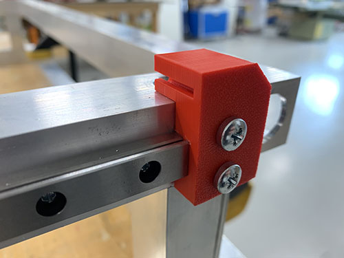
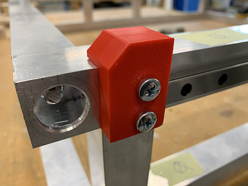
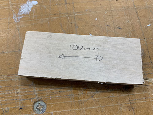
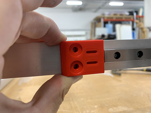
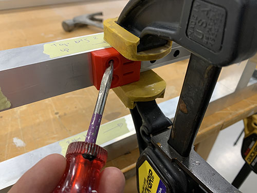
2x belt tension sliders (P17, P26) were attached on the opposite side of the fixed belt tensioners, ontop of the aluminium profile, using 4x 20mm M5 screws (S12). To get them aligned at the exact same place on both sides, a 100 mm distance was cut out and a flat support was clamped to the inner side of the profile. The same drill and tap size were used as for the fixed belt tensioners (4mm drill, M5 drill tap). Make sure that the belt tension sliders are pointing outwards.
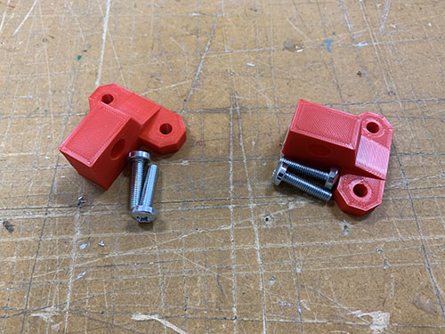
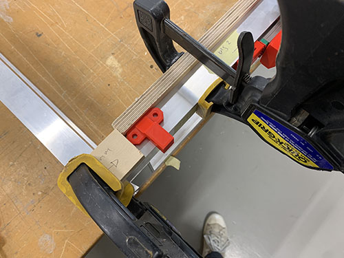
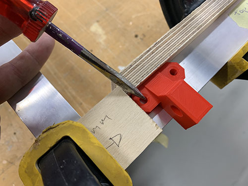
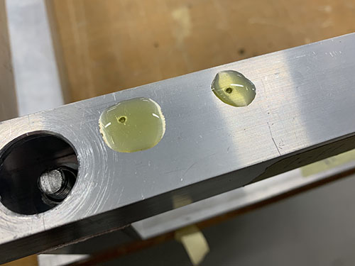
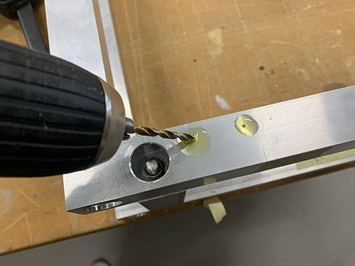
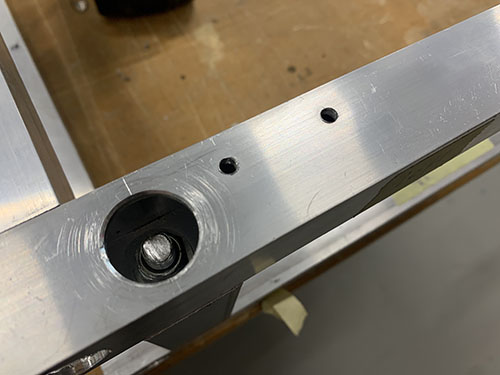
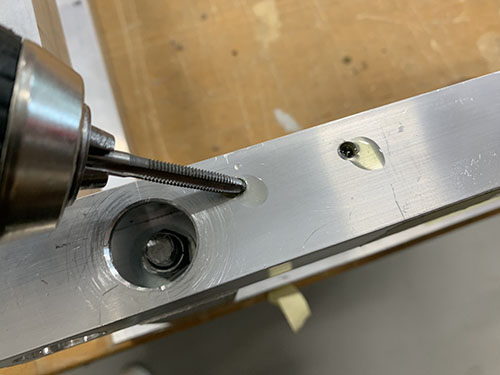
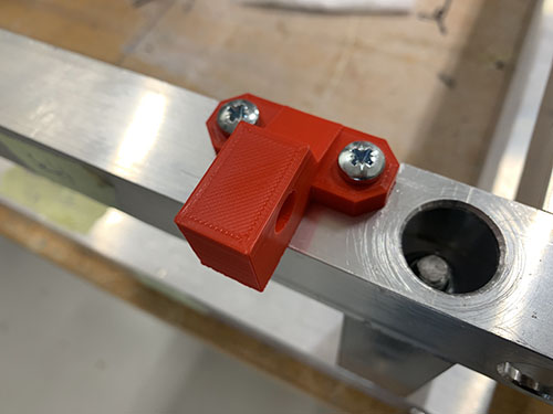
2x end-stop mounts (P08) were then attached to the same side as the belt tension sliders using 4x 20mm M5 screws (S12), facing outwards and aligned with the rails. The same drill and tap size were used as for the fixed belt tensioners (4mm drill, M5 drill tap).
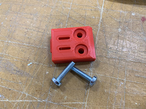
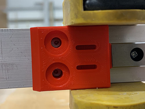
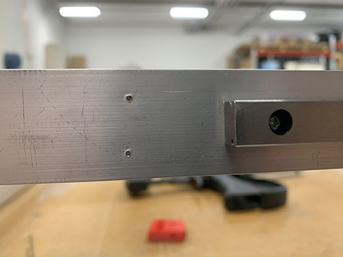
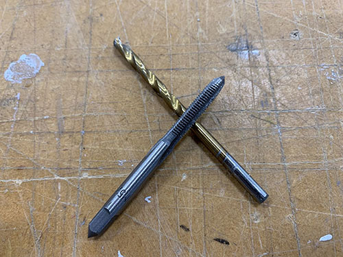
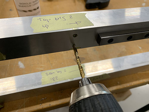
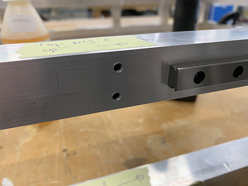
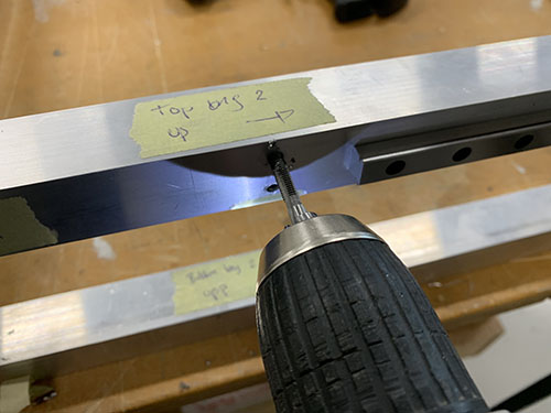
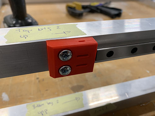
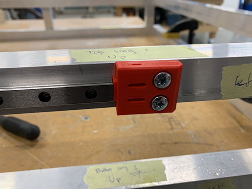
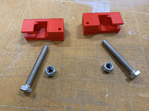
The belt tensioners (P18, P27) were loosely attached to the belt tension sliders using 2x 60 mm fully threaded M8 screws (S15), 2x M8 nuts(N03) and 2x (20mm x 10mm x 2mm) washers (W04).
Y-axis HTD5M belts
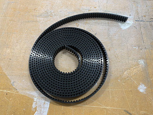
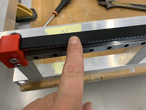
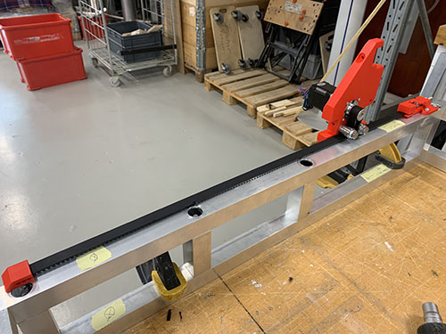
The HTD5M belt (O17) was first inserted into one of the fixed belt tensioners using a flat screw driver. It was then stretched along the aluminium profile, below the first idler, around the timing pulley, below the second idler and all the way to the belt tensioner.
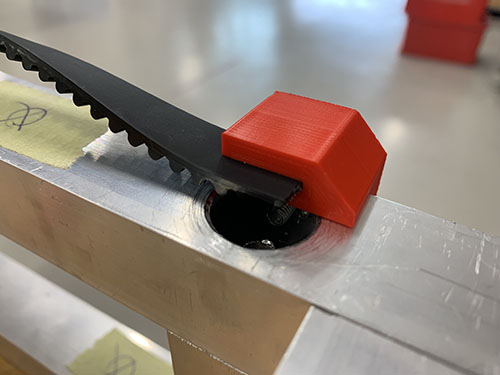
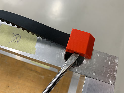
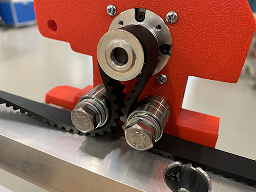
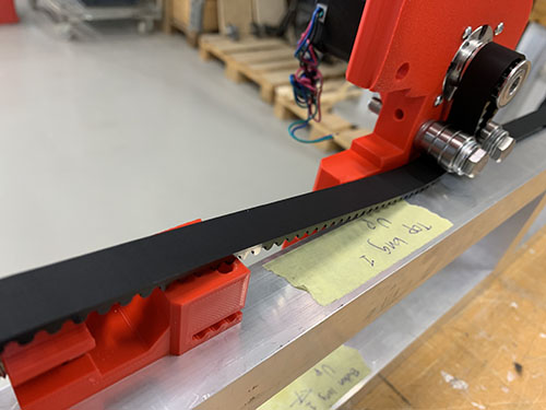
A scissor was used to cut the belt at an appropriate length. The loose end was then inserted into the belt tensioner using a flat screw driver and the belt was stretched by tightning the M8 nut.
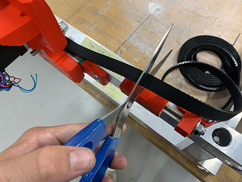
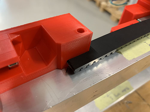
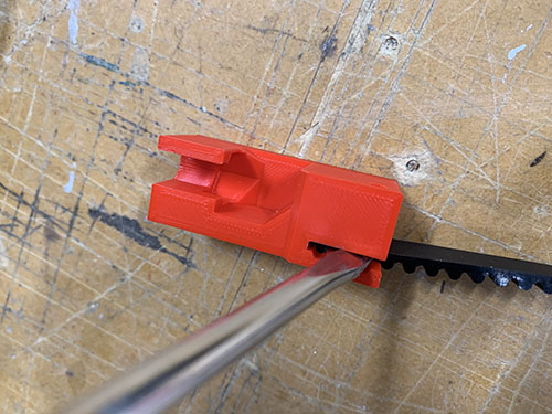
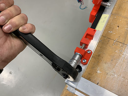
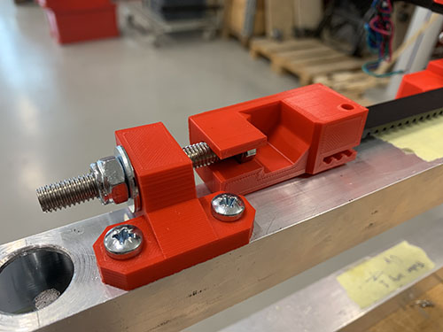
Make sure that the belt is not too loose and not too tight.
Repeat on the other side.
X-axis and Z-axis
Rails to bridge beams
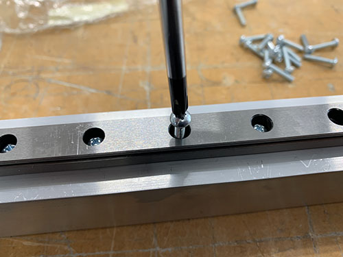
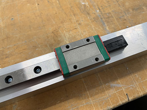
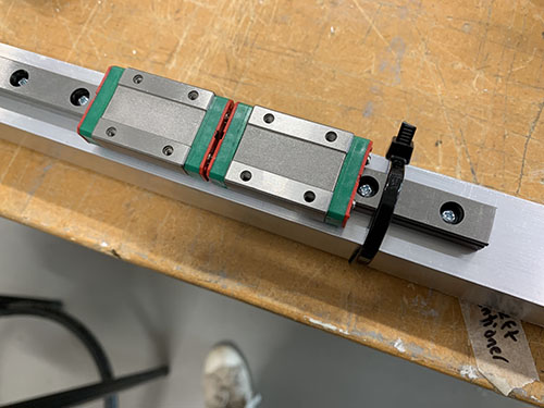
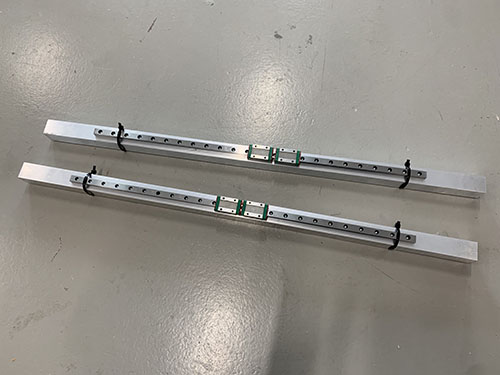
The last two 600 mm MGN12H rails (O21) were attached to two of the 803 mm aluminium bridge beams (O05, used for the X-axis). First, the MGN12H blocks (O22) were carefully removed from the rails.
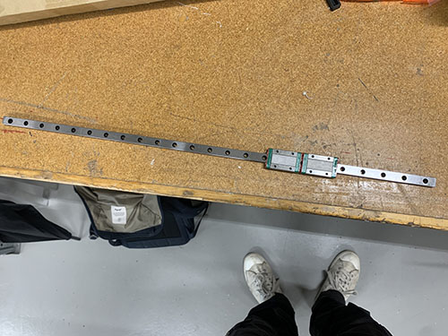
The same 100 mm distance used to align the belt tension sliders were used to align the rails. Because they will be off center by 3 mm, make sure that you later attach the bridge beams to the side plates in a way so the rails line up.
The same 3d-printed support tools (P25) used to align the rails on the 900 mm aluminium profiles were used here as well. Everything was clamped into position. A bradawl and a hammer were used to make indentations and a 2 mm drill and a M3 drill tap was used to make the screw holes.
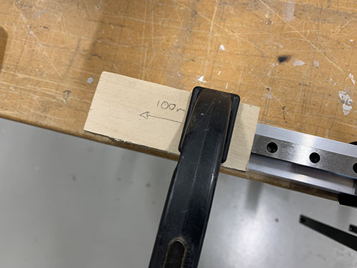
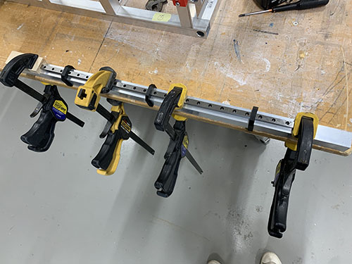
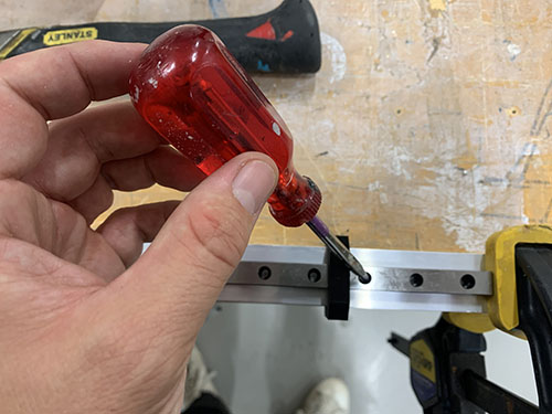
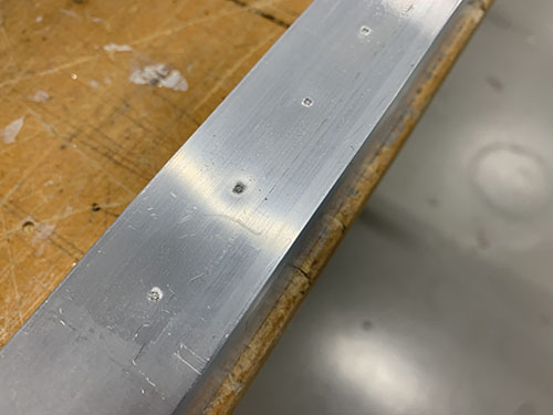
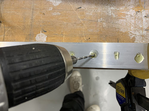
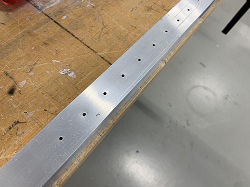
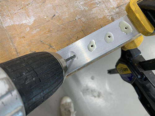
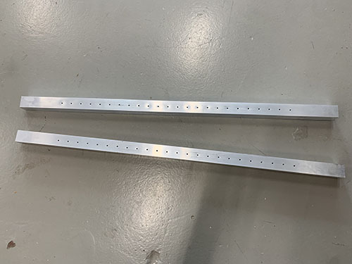
The rails were finally attached using 16 mm M3 screws (S03) and the MGN12H rail blocks (O22) were gently slided back onto the rails.
X-axis tensioner and end-stop mount to lower bridge beam
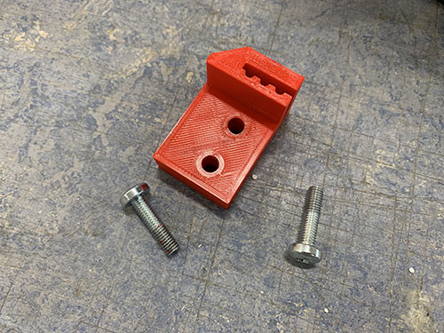
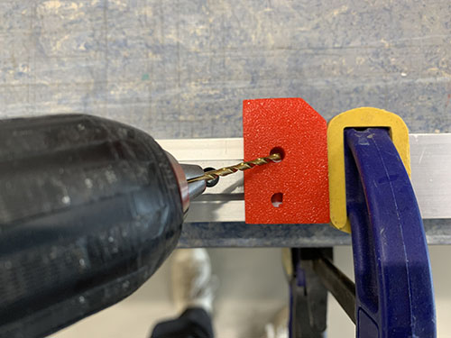
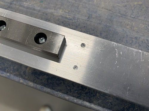
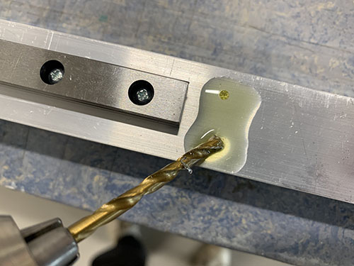
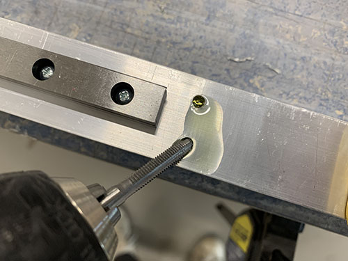
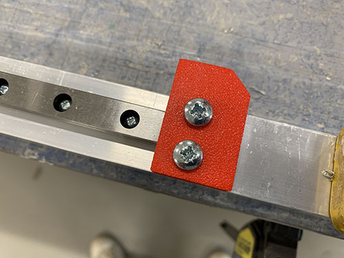
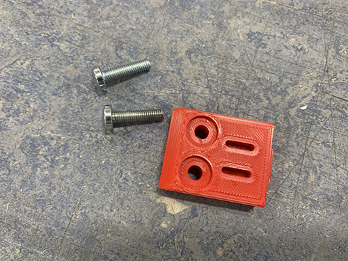
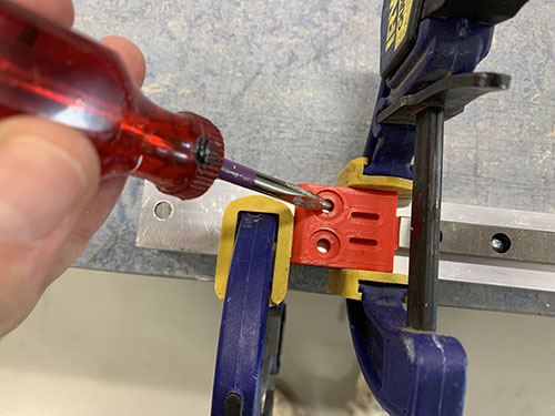
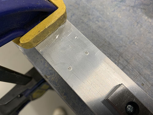
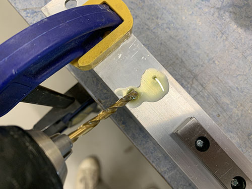
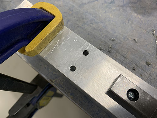
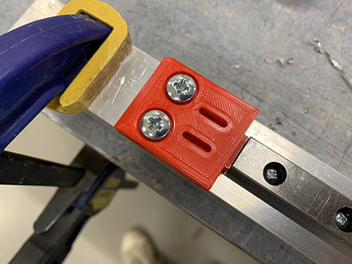
The fixed tensioner (P28) and end-stop mount (P08) were attached to the lower bridge beam in the same fashion as on the 900 mm aluminium profiles, using 4x 20mm M5 screws (S12). When aligning the fixed tensioner, make sure that the "belt opening" is pointing in the direction of the rail. A bradawl and a hammer were used to make indentations at the center of the holes. Cutting fluid was applied and a 4 mm drill was used to drill the holes, followed by a M5 drill tap.
Bridge beams to side plates
All three bridge beams (O05) were then inserted into the slots on the side plates. Make sure that the two beams with the rails are on top of each other, with the rails pointing outwards. Also, make sure that you insert them in the correct orientation, so that the rails are lined up (due to the rails being 3 mm off center).
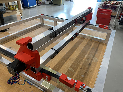
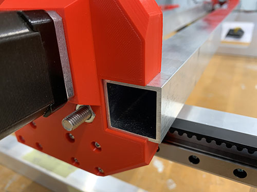
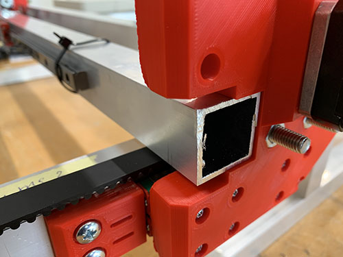
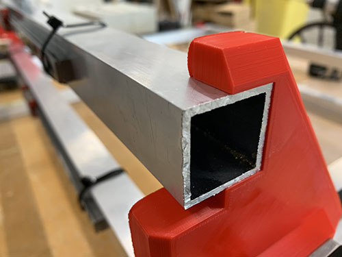
When the bridge beams were aligned, the blocker clips (P21, P22, P23, P30, P31, P32) were placed in their correct place and a sharpie was used to mark the center of the holes to be drilled. Similar to before, a bradawl and a hammer were used to make indentations at the center of the holes.
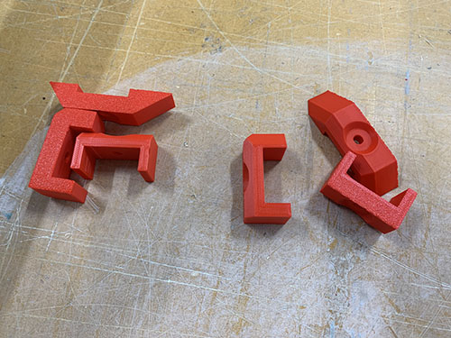
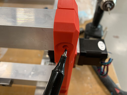
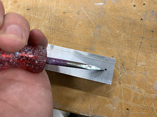
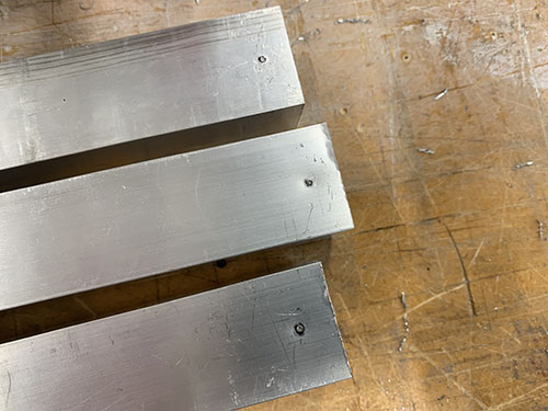
A 7 mm drill bit was used to drill the holes. As these holes were going straight through the profiles, a bench drill was used for precision. A metal file was used to remove all excess metal around the holes.
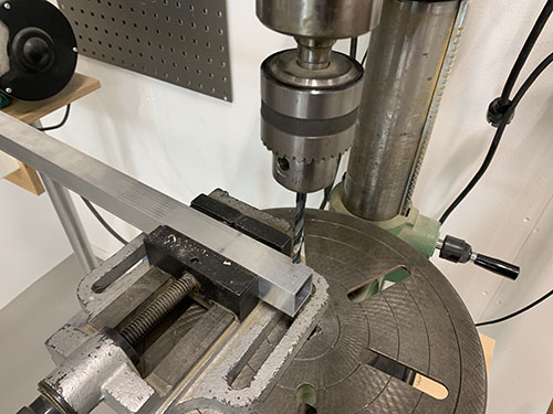
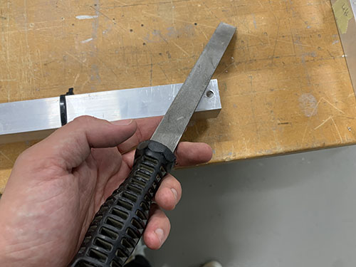
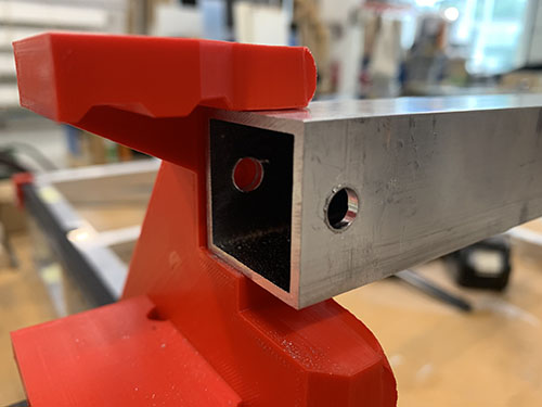
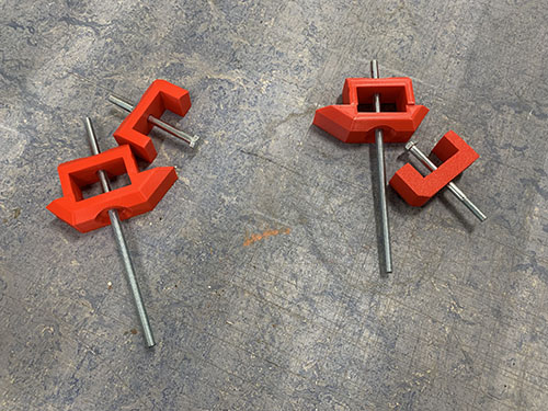
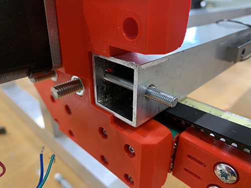
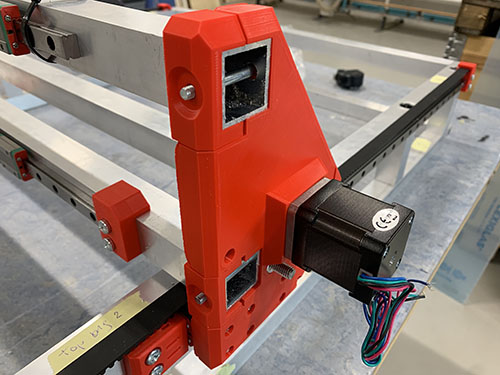
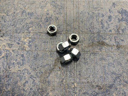
The bridge beams were then inserted into the slots on the side plates once more, along with all the blocker clips. 2x 140 mm threaded M5 rod (T01) was inserted through the bottom two beams and 2x 60 mm M5 (S14) screws was inserted through the top bridge beam. It was all tightened using M5 nuts (N02).
Rod bearings to carriage
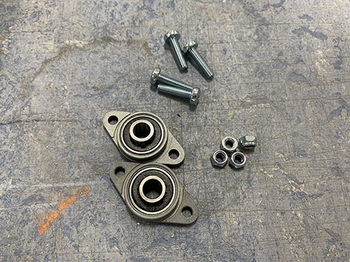
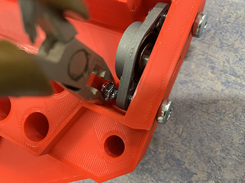
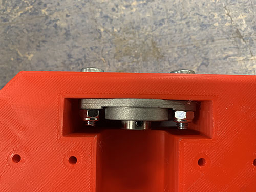
Before attaching the carriage (P07) to the bridge beams, two KFL08 rod bearings (O19) were attached on the top and the bottom of the carriage (inside) using 4x 20 mm M5 screws (S12) and 4x M5 nuts (N02). A tip is to temporarily use the acme rod (used in an upcoming step) to vertically align the two bearings.
Carriage to bridge beams
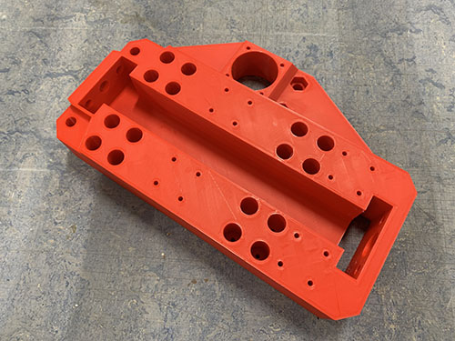
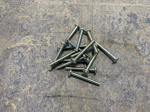
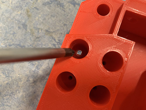
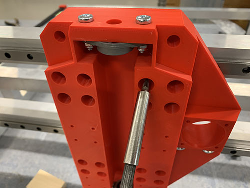
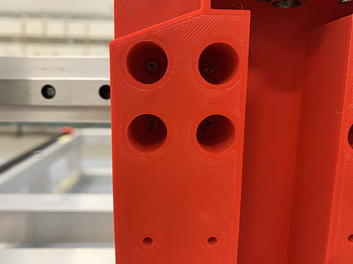
The carriage was attached to the 4x MGN12H blocks (O22) on the bridge beams, using 16x 25 mm M3 screws (S05).
X-axis motor, idlers and pulley to carriage
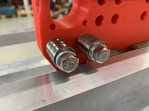
Each idler were made up out of 1x 60 mm fully threaded M8 screw (S15), 3x 698zz bearings (O01) and 4x (15 mm x 8.5 mm x 1.5mm) washers (W03) (1 closest to the idler blocker and 3 closest to the side plate). 2x idlers were then attached to each side plate using 2x M8 nuts (N03). Make sure that the bearings are spinning freely.
As I designed and added the idler blocker later on in the build, some of the images doesn't have it and they also have 3 washers instead of 1 washer closest to the screw head. I left these images anyways in the guide so you can see how it looks when you attach the idlers, but please ignore the wrong number of washers. Also ignore all the other things around the idlers in the upcoming image, they are taken later on in the build.
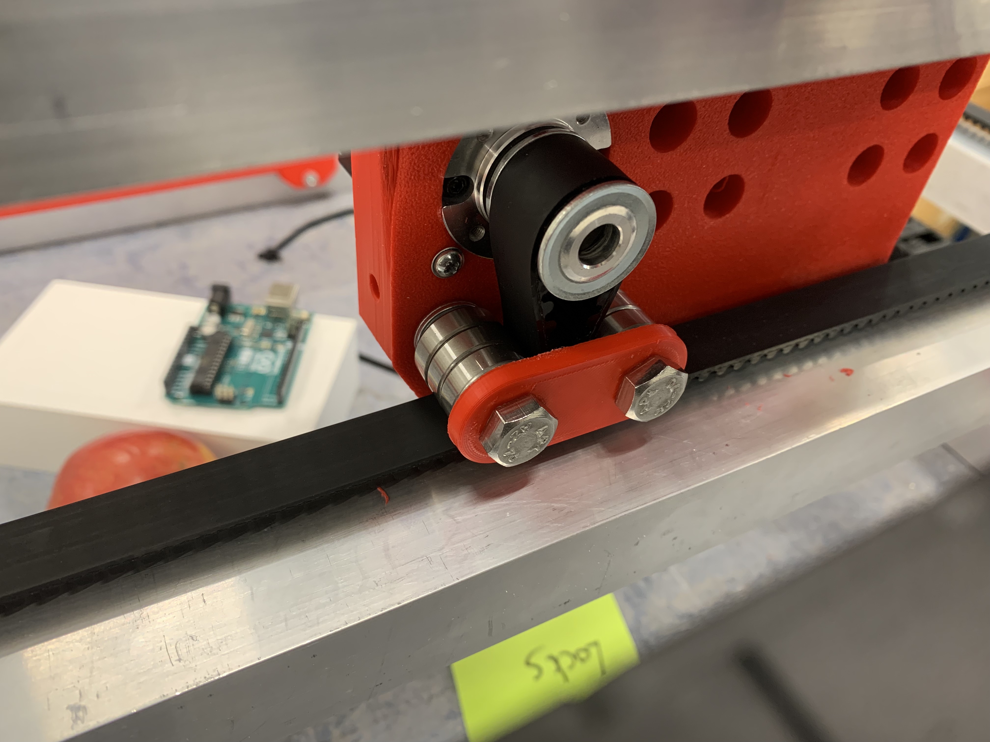
Should be idler blockers and a different number of washers in the upcoming images.
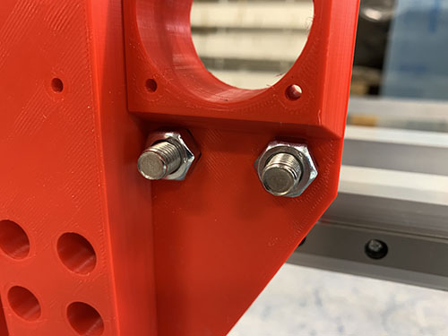
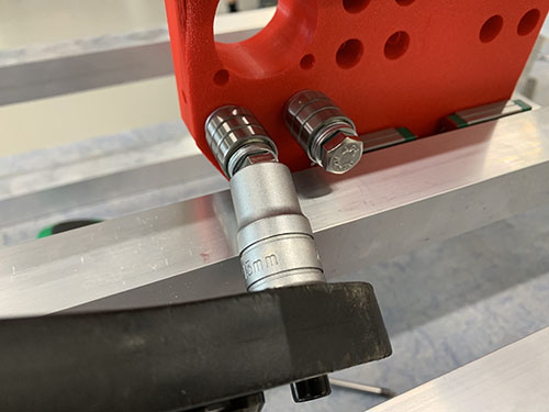
To attach the stepper motor to the carriage, the 4x M3 screws locking the gear box to the motor were removed.
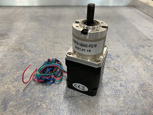
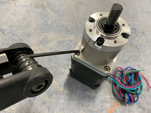
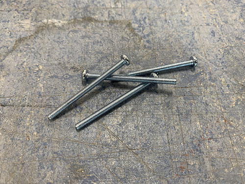
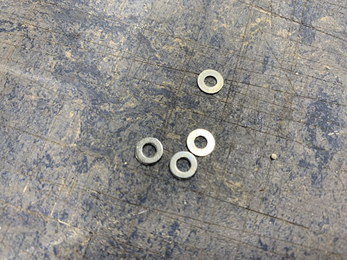
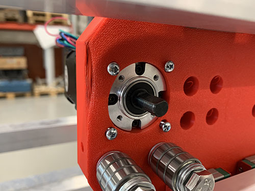
The stepper motor was then inserted into the large hole on the carriage, facing towards the bridge beams/idlers. 4x 40 mm M3 screws (S06) and 4x M3 washers (W05) were used to lock the stepper motor onto the carriage. The motor should be attached so that the cables are facing upwards.
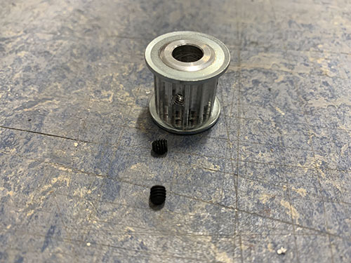
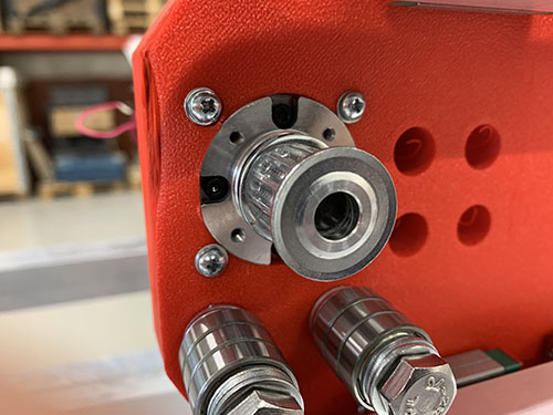
1x HTD5M timing pulley (O18) was attached to the motor shaft using set screws.
X-axis HTD5M belt
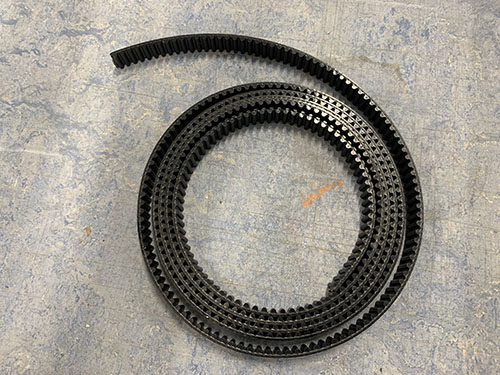
The HTD5M belt (O17) was first inserted into the fixed belt tensioner using a flat screw driver. It was then stretched along the aluminium profile, below the first idler, around the timing pulley, below the second idler and all the way to the other side.
The belt was cut at an appropriate length and inserted into the belt tensioner (P27) using a flat screw driver.
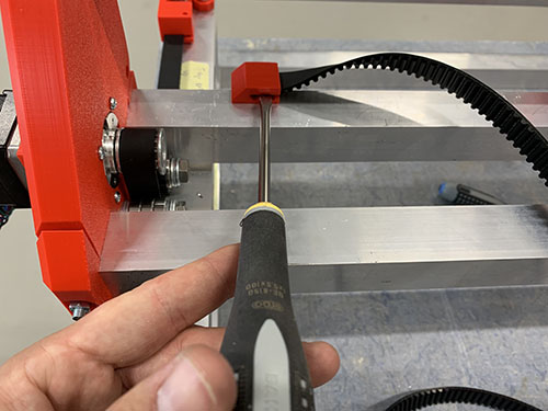
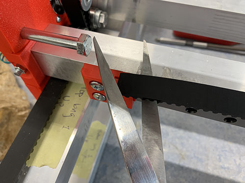
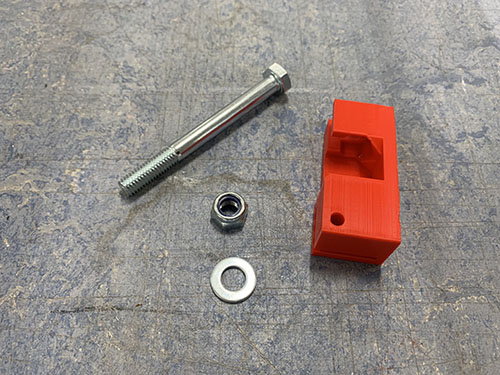
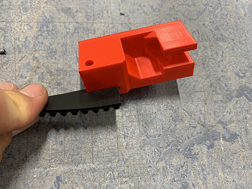
The belt tensioner was then attached to the side plate using 1x 60mm fully threaded M8 screw (S15), 1x M8 nut (N03) and 1x (20mm x 10mm x 2mm) washer (W04). The M8 screw in the image is not fully threaded as I lost the one I was suppose to use and had to use another one, so please ignore :)
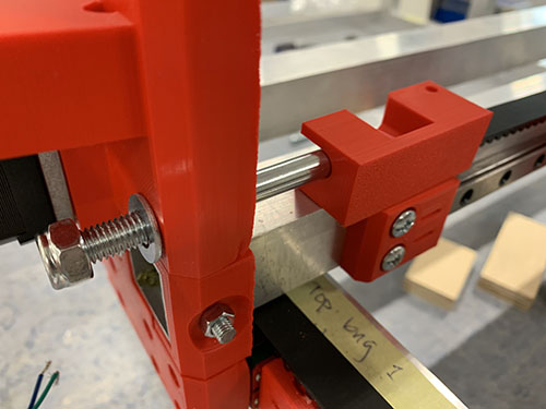
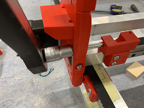
Make sure that the belt is not too loose and not too tight.
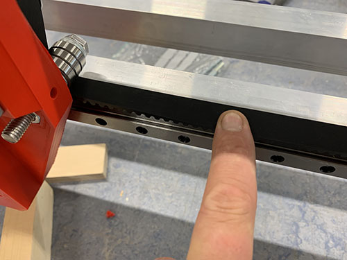
Acme nut and rails to carriage slider
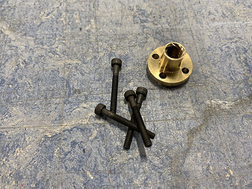
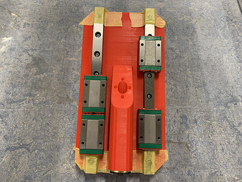
1x acme nut (O03) was inserted from the outside, into the the center hole at the top of the vertical carriage slider (P36). It was locked in place using 4x 25mm M3 screws (S05).
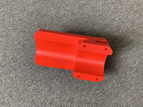
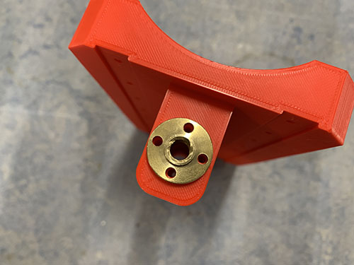
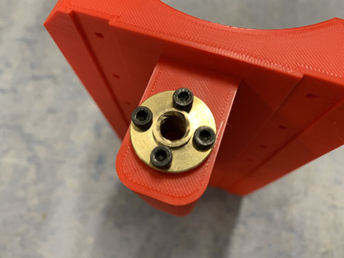
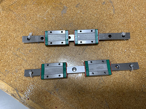
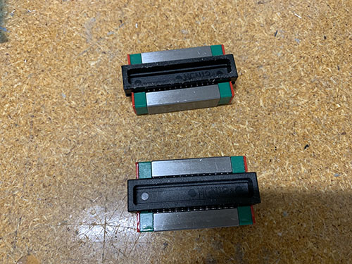
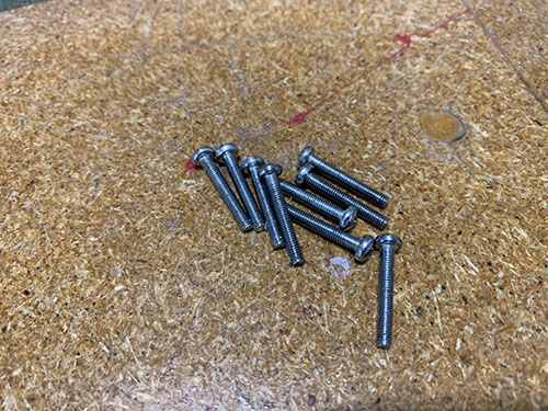
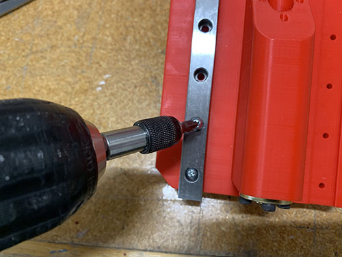
2x smaller 200 mm MGN12H rails (O20) were then attached to the back of the vertical carriage slider. First, the MGN12H blocks (O22) were carefully removed from each rail. After that, the rails were screwed in place on the back of the vertical carriage slider using 16x 20 mm M3 screws (S04). The MGN12H blocks were then slided back on and each end were blocked using tape.
Acme rod and vertical slider to carriage
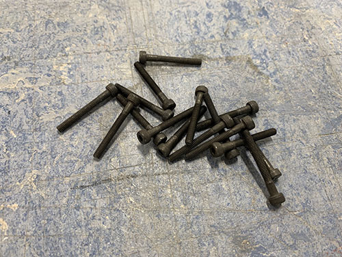
To attach the vertical slider to the carriage, 16x 25 mm M3 screws (S05) were first inserted into the holes on the carriage. You might need to "open up" the holes using a narrow tool (depending on the direction you 3d-printed the carriage).
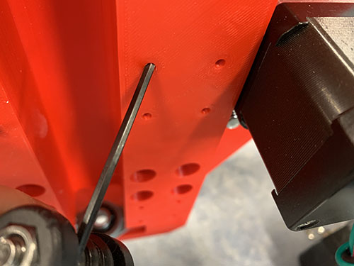
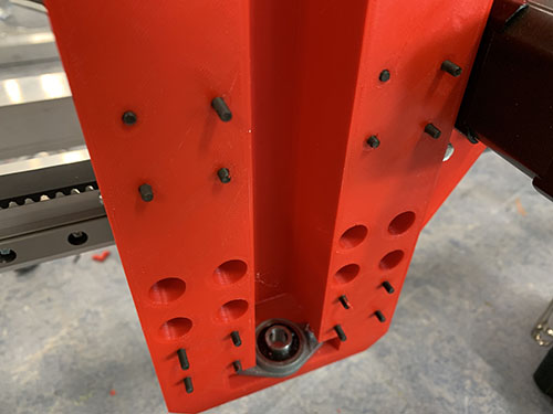
1x acme rod (O02) was then inserted through the two KFL08 rod bearings and the acme nut, and the set screws on the bearings were tightened.
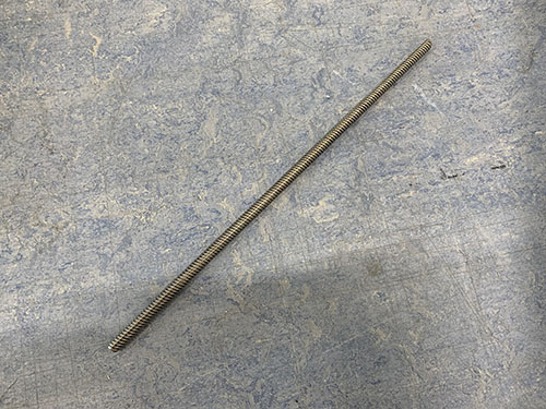
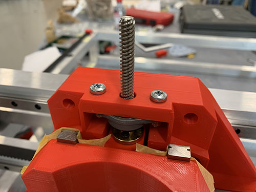
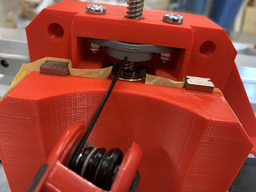
The vertical slider was finally attached to the carriage by attaching the previously mentioned 16x 25 mm M3 screws (S05) to the MGN12H blocks on the vertical slider.
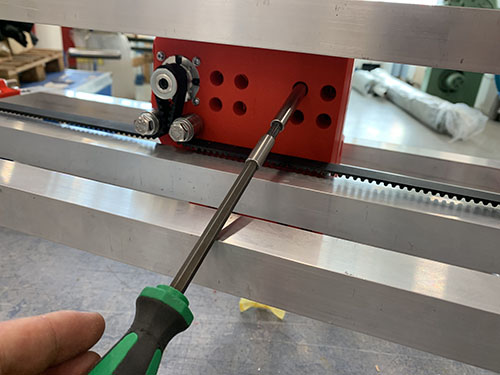
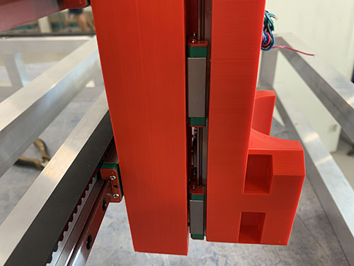
Z motor mount and X-axis cable chain
The first step was to find a good length of the X-axis cable chain (O09). To simplify this process, the X-axis belt was removed to easier move the carriage along the X-axis.
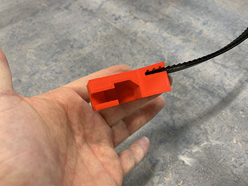
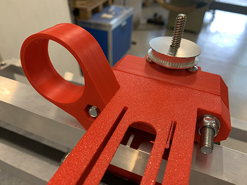
The Z motor mount (P40) and the X-axis cable chain mount (P38) were then attached using 3x 25 mm M4 screws (S10), 3x M4 nuts (N01) and 3x (10mm x 5mm x 1mm) washers (W01).

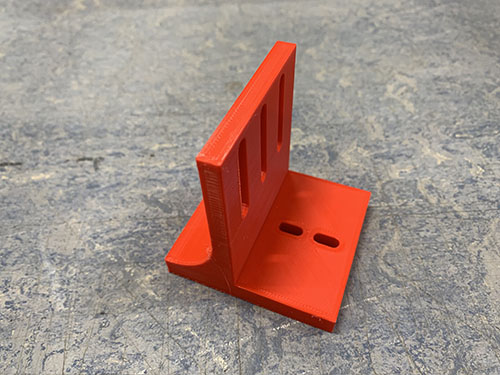
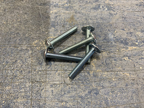
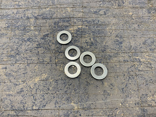
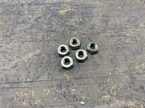
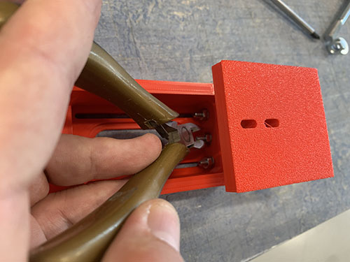
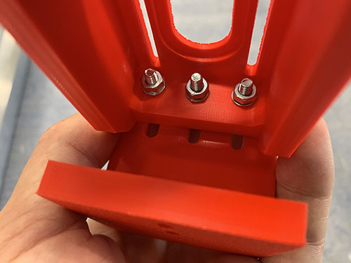
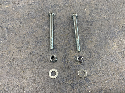
They Z motor mount was then attached to the carriage using 2x 80mm M8 screws (S16), 2x M8 nuts (N03) and 1x (20mm x 10mm x 2mm) washers (W04). The vaccum mount was also inserted and attached to the right-side M8 screw. Please ignore the timing pulley attached to the acme rod in some of the images, it will be attached in a later step.
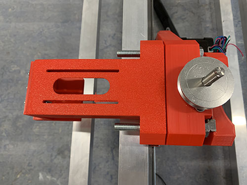
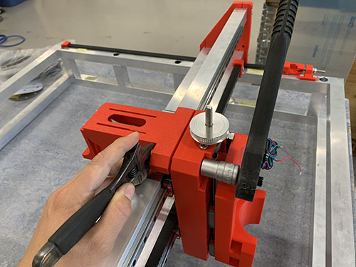
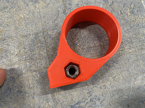
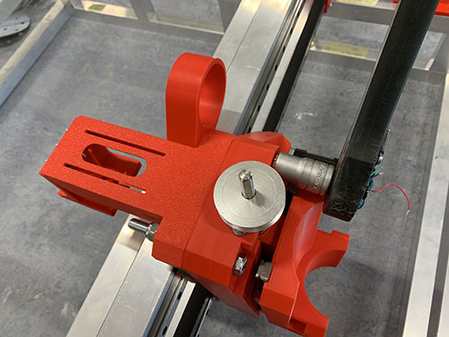
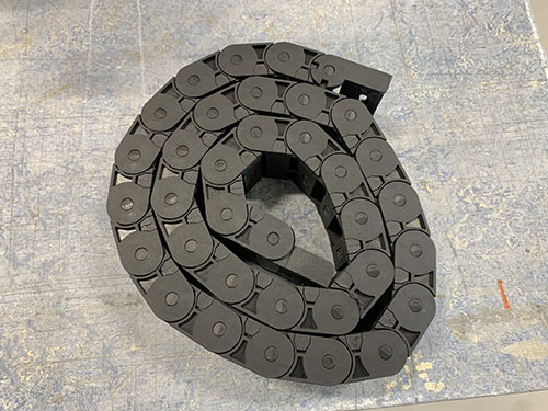
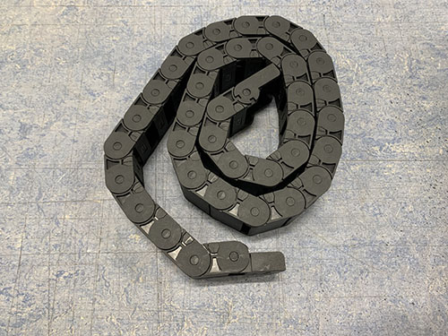
1x 1 meter cable chain (O09) were then clamped to the cable chain mount and to the back-side bridge beam. The carriage was then moved as far to the sides as possible. It's important that the chain doesn't touch any of the side plates when moved. In my case, I had to remove 3 links from the cable chain to get a good length of the chain.
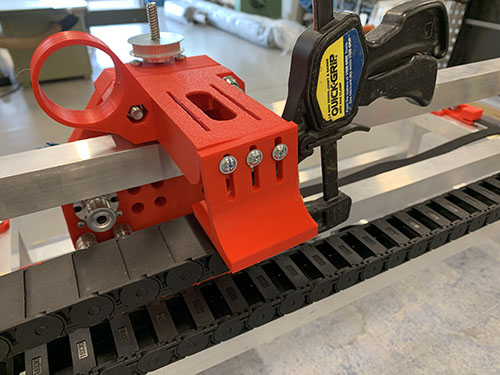
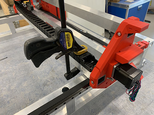
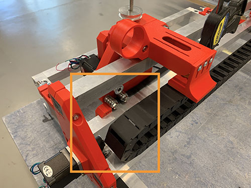
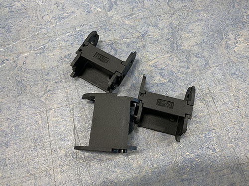
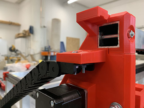
The Z motor mount and cable chain mount were then disassembled and the cable chain was properly attached to the cable chain mount using 2x 25mm M4 screws (S10), 2x M4 nuts (N01) and 2x (10mm x 5mm x 1mm) washers (W01).
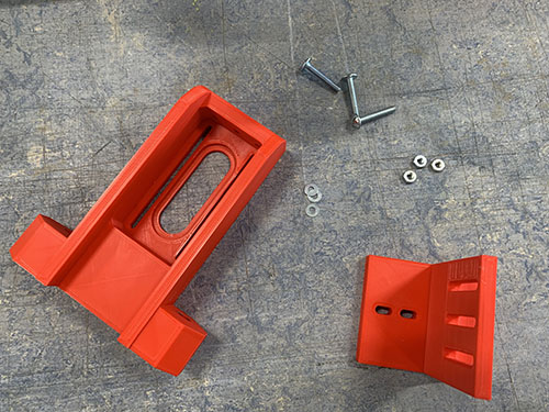
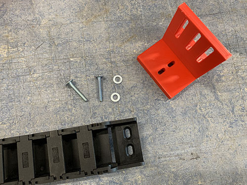
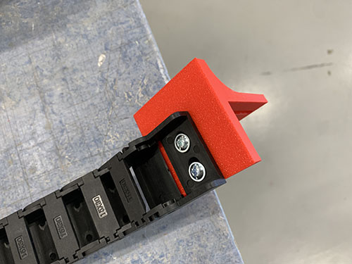
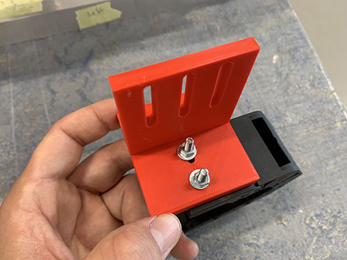
The Z motor mount and cable chain mount were then assembled again and attached to the carriage in the same fashion as before.
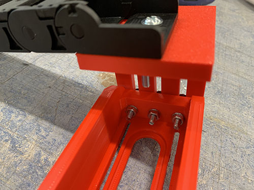
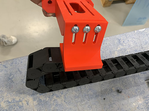
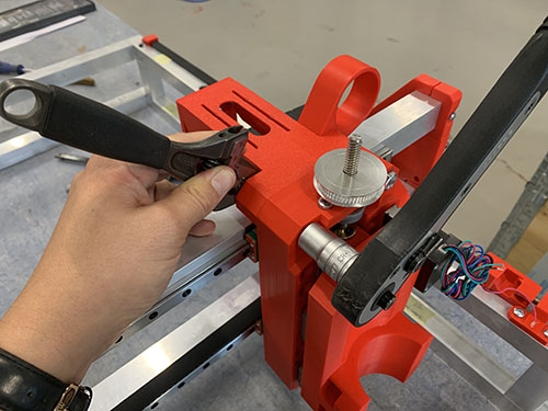
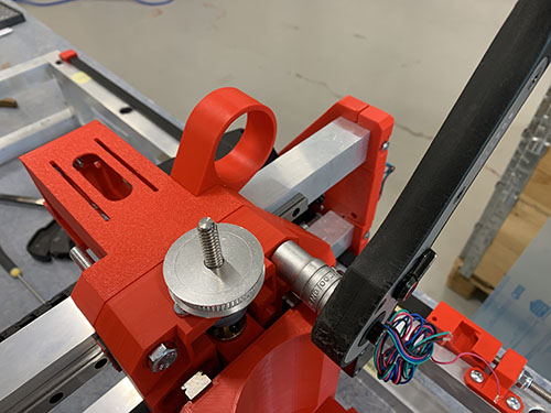
The carriage was move all the way to the right side plate and the cable chain was clamped to the lower back bridge beam.
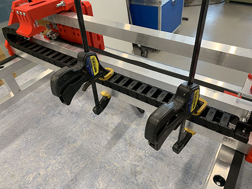
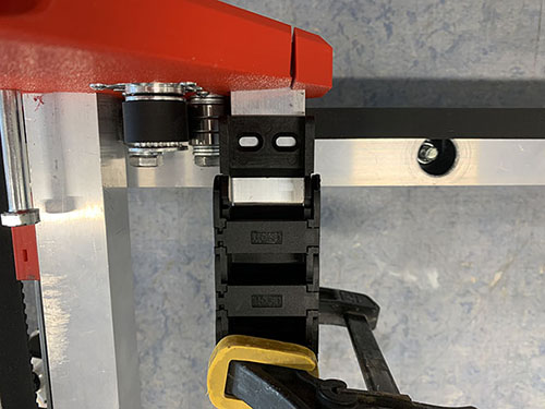
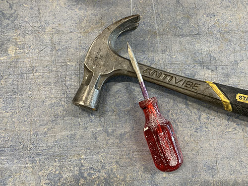
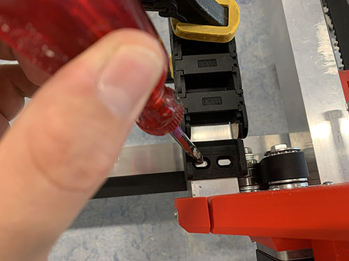
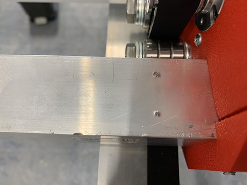
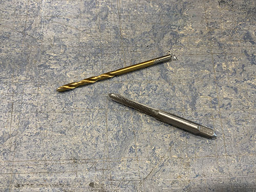
A bradawl and a hammer were used to make indentations at the center of the two holes. Cutting fluid was applied and a 3 mm drill was used to drill the holes, followed by a M4 drill tap. The cable chain was then attached to the bridge beam using 2x 25 mm M4 screws (S10).
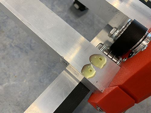
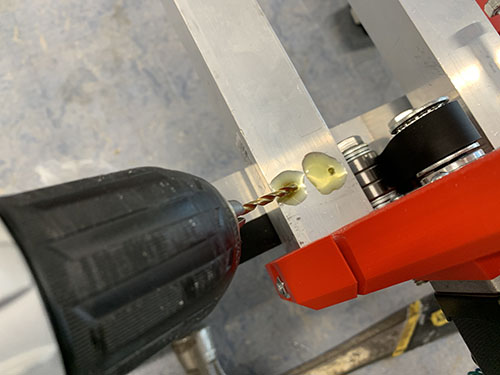
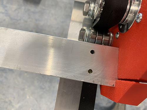
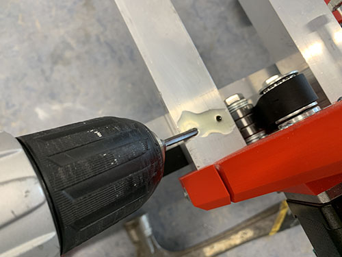
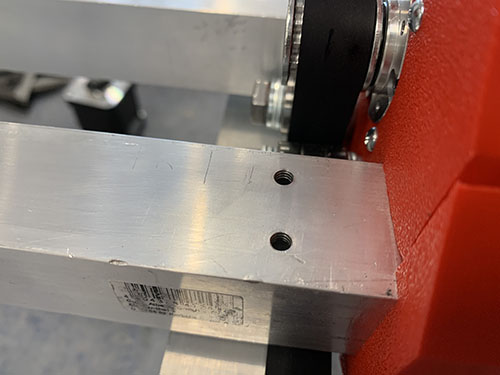
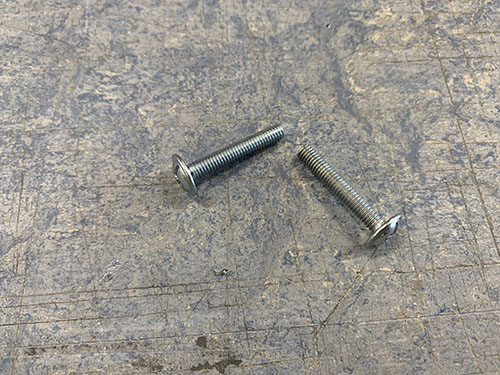
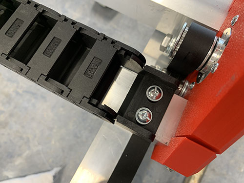
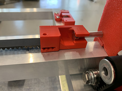
Finally, the X-axis belt was reattached and tightened.
Y-axis cable chain
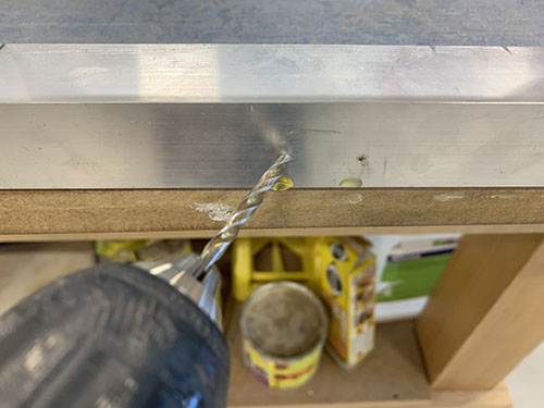
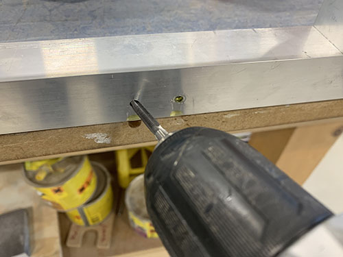
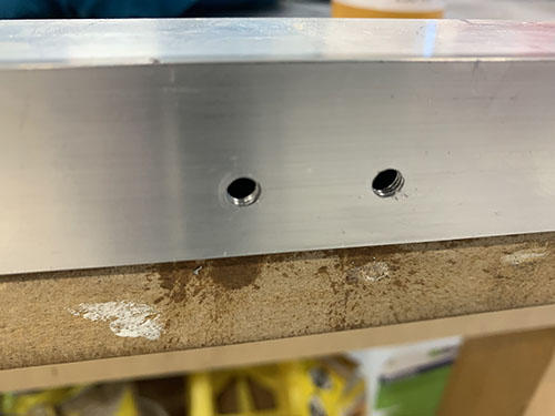
The Y-axis cable chain (O09) was attached to the frame using 1x cable chain mount (P05) and 1x cable chain support (P06). The cable chain mount was clamped to the left side of the lower frame and aligned with the last vertial beam. A bradawl and a hammer were used to make indentations at the center of the two holes. Cutting fluid was applied and a 4 mm drill was used to drill the holes, followed by a M5 drill tap. The cable chain mount was then attached to the lower frame using 2x 20 mm M5 screws (S12).
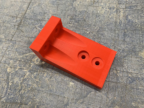
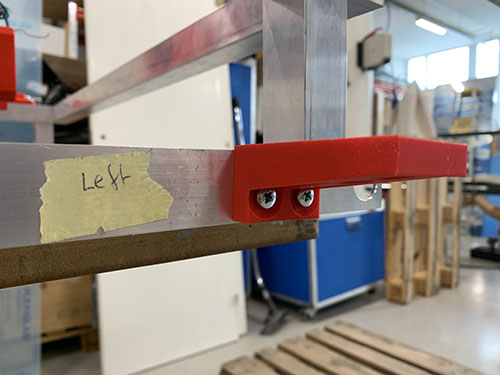
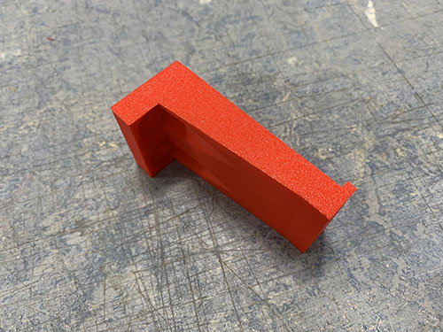
The cable chain support was only attached to the lower frame for the cable chain to rest on. It was aligned and attached it at the center between the second and third vertical beam. Make sure that it does not go below the bottom frame!
In the same way as the cable chain mount, a bradawl and a hammer were used to make indentations at the center of the two holes. Cutting fluid was applied and a 4 mm drill was used to drill the holes, followed by a M5 drill tap. The support was then attached to the lower frame using 2x 20 mm M5 screws (S12).
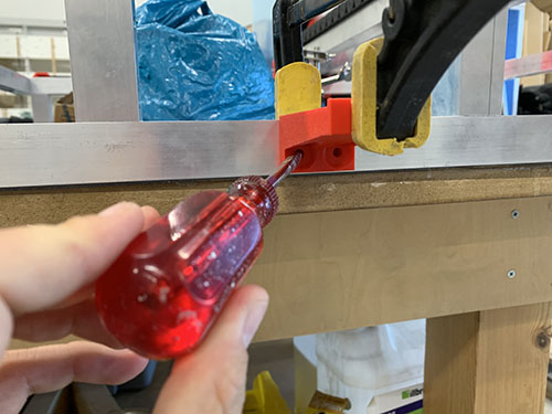
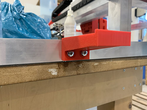
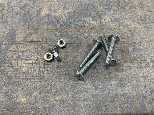
The Y-axis cable chain (O09) was then attached to the left side plate (P20) and lower frame support using 4x 25 mm M4 screws (S10), 4x M4 nuts (N01) and 4x (10mm x 5mm x 1mm) washers (W01).
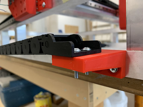
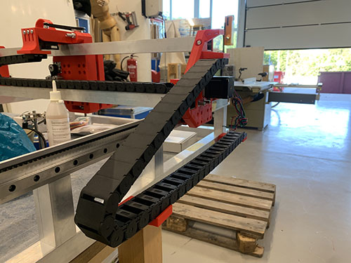
Z stepper motor, pulleys and belt
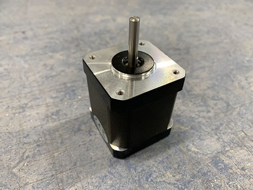
The non-geared NEMA17 stepper motor (E11) was attached to the Z-axis motor mount using 4x 8mm M3 screws (S08) and 4x M3 washers (W06). Make sure that the motor cable connector is pointing in the same direction as the opening of the X-axis cable chain.
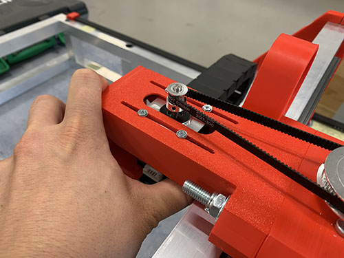
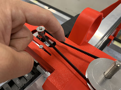
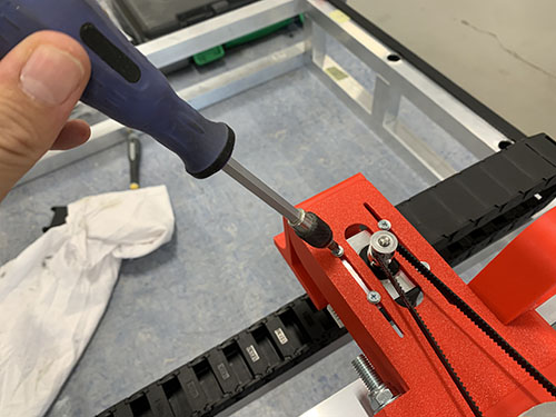
1x 16 teeth GT2 timing pulley (O15) was then attached to the motor shaft and 1x 60 teeth GT2 timing pulley (O16) was attached to the acme rod. Both were locked in place using set screws. Make sure that they line up.
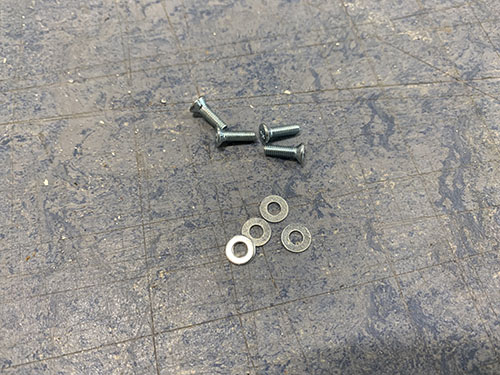
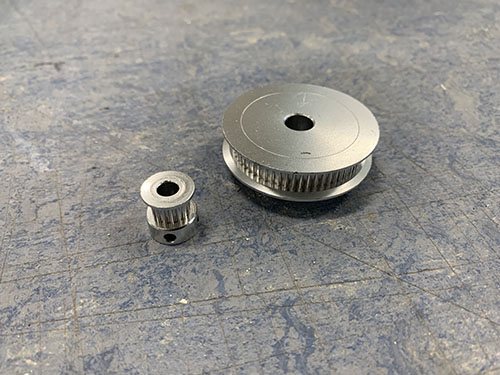
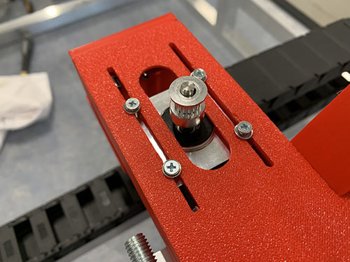

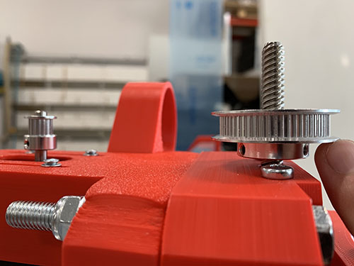
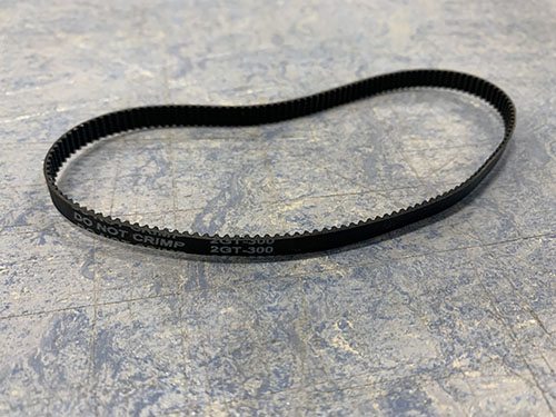
1x GT2 timing belt (O14) was looped around both timing pulleys and stretched. Before tightning the M3 screws and locking the motor into place, make sure that the belt is not too loose and not too tight.
Stepper motors and end-stops
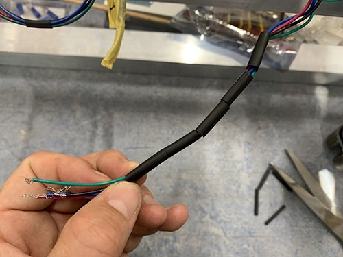
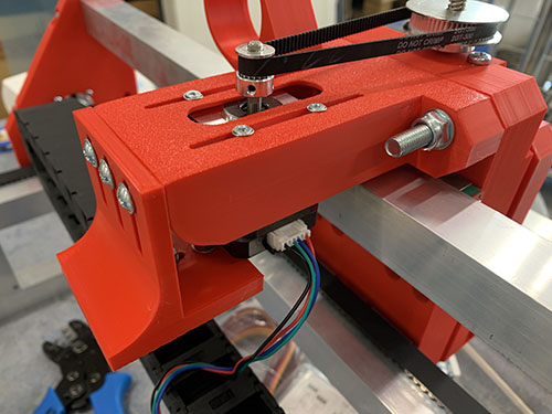
Extend stepper motor wires
All 4 stepper motors (2x Y-axis, 1x X-axis and 1x Z-axis) get their power and movement instructions from the Arduino + CNC shield that in a later step will be attached in the small electronic box. Therefore, the stepper motor cables needed to be extended to reach through the cable chains all the way to the front of the machine, where the small electronic box will be located.
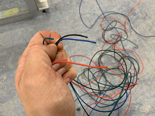
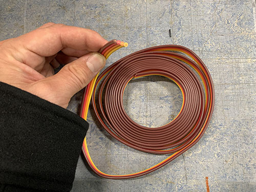
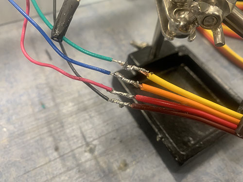
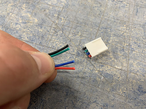
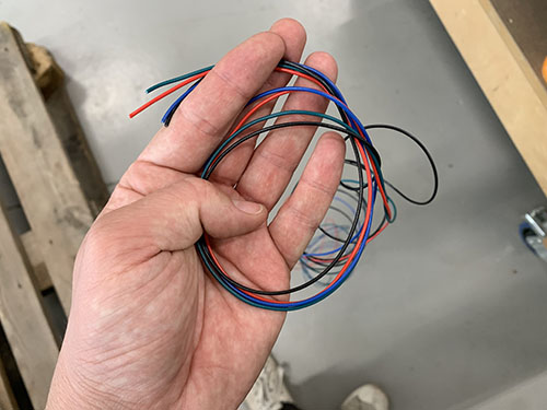
AWG22 cables (E08) of matching colors were used when increasing the length of the stepper motor cables. The same process was used for all the motors:
- The amount of wires needed to reach all the way to the electronic box was approximated and cut. Make sure to have an extra ~300 mm wire from the point where the wires exits the Y-axis cable chain, as this will be needed to reach the small electronic box.
- The ends of the original stepper wires and the extra AWG22 wires were stripped using a wire stripper.
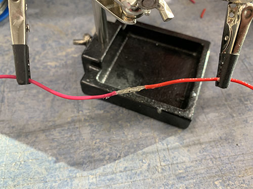
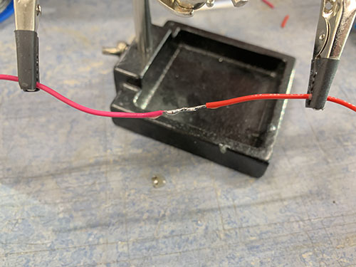
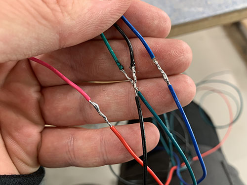
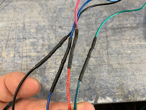
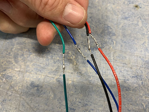
- The colors of the original stepper wires and the extra AWG22 wires were matched up and the stripped ends of the wires were twisted around each other.
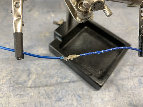
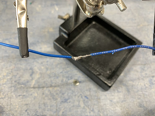
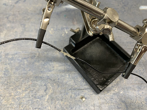
- The twisted wires where then locked in a steady position by a "third hand".
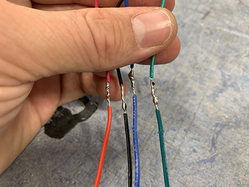
- Soldering grease was applied to the twisted wires and the wires were soldered together.
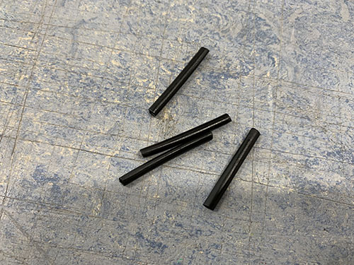
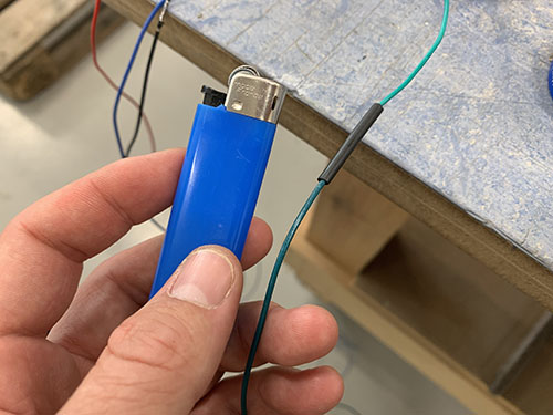
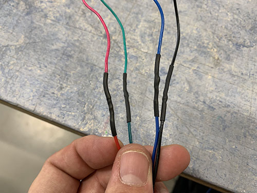
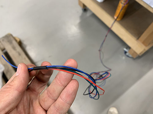
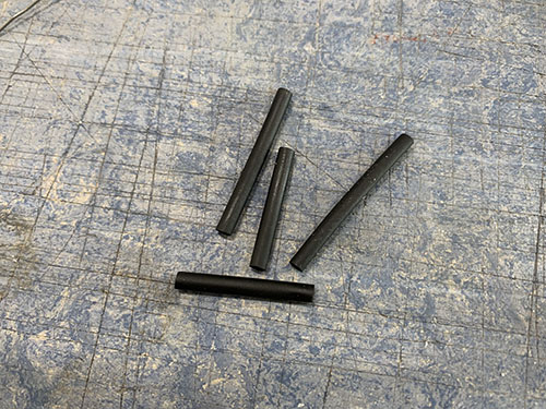
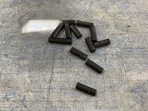
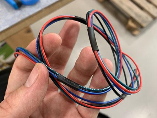
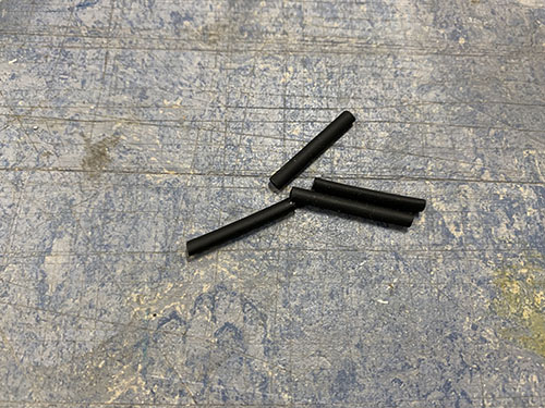
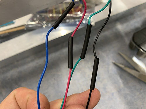
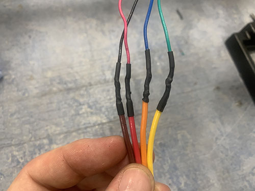
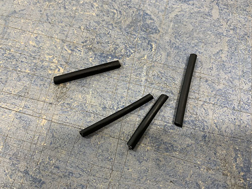
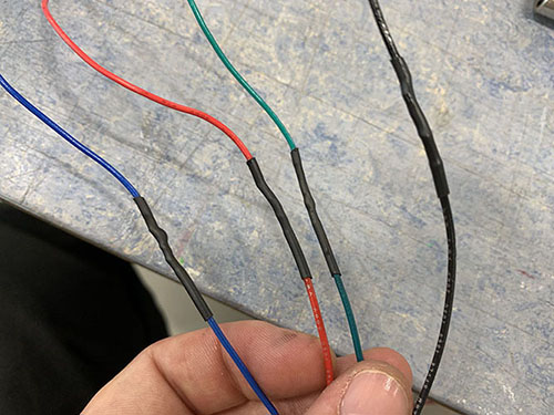
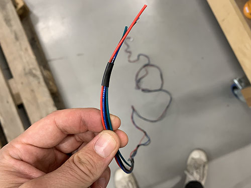
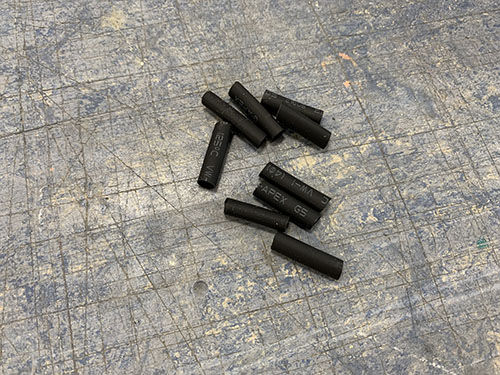
- 4 shrinking tubes (one per cable) were shrunk around the now soldered twisted wires, covering the soldering.
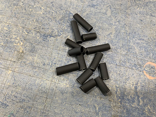
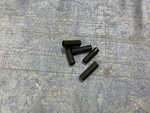
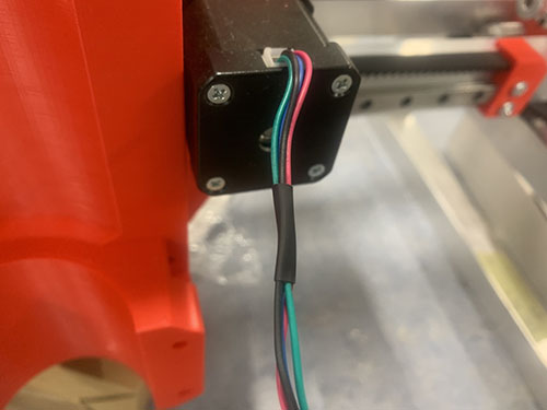
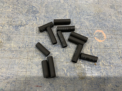
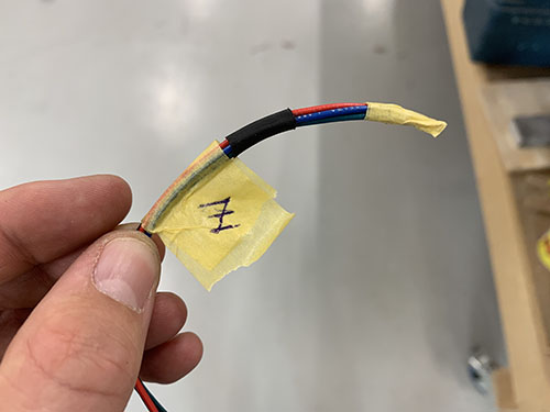
- A handful of larger shrinking tubes were shrunk around all 4 wires to keep them together.
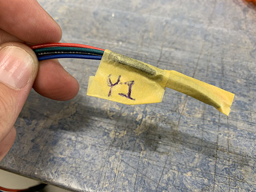
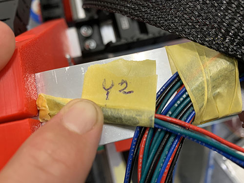
- Finally, the wires were marked using tape and a penn, indicating which stepper motor the wires belonged to. This is important as it will help a lot later on, when the stepper motors are connected to the Arduino.
Y-axis 1
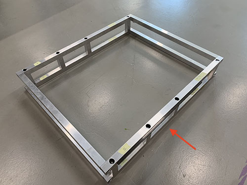
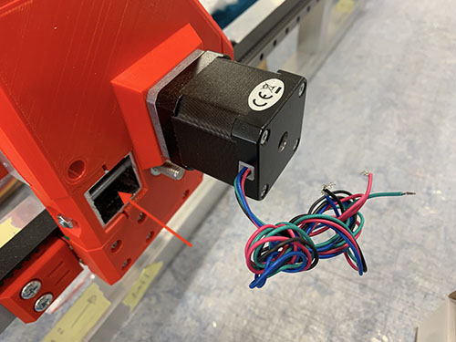
The extended wires of the first Y-axis stepper motor were cut at a length so that they reached through the lower front bridge beam (see red arrow on the next image) and through the Y-axis cable chain going to the front of the CNC machine.
Y-axis 2
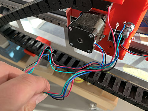
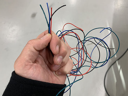
The extended wires of the second Y-axis stepper motor were cut at a length so that they reached through the Y-axis cable chain going to the front of the CNC machine.
X-axis
I ran out of AWG22 wires when soldering the X-axis stepper motor cables, therefore you will see different type of cables in the upcoming images. Because of this, I had to insert the shrinking tubes before I soldered the cables. Please disregard this and follow the previous instructions.
The extended wire of the X-axis stepper motor were cut at a length so that they reached up and behind the Z-axis stepper motor, through the X-axis cable chain and through the Y-axis cable chain to the front of the CNC machine.
Z-axis
The non-geared NEMA17 motor used for the Z-axis had removable wires, in contrast to the 1:19 geared NEMA17 motors that had non-removable wires. The first step was therefore to connect the wires to the NEMA17 motor and cut of the connector on the other side using a scissor. Otherwise, the same procedure was followed as for the other motors.
The extended wires of the Z-axis stepper motor were cut at a length so that they reached through the X-axis cable chain and through the Y-axis cable chain to the front of the CNC machine.
End-stops and end-stop wires
End-stops are important, as they do not only enable you to home the CNC machine, but they also limit the CNC machine from moving past what is physically possible. When the end-stops are triggered, an alarm is fired and the machine automatically stops.
The wires used for end-stops were 0.75 mm^2 (E03).
X-axis (max)
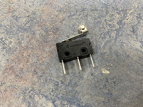
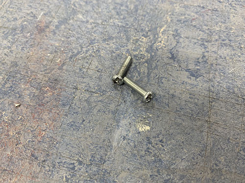
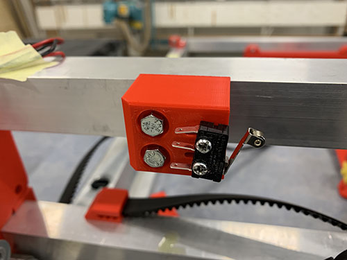
A microswitch (E21) was attached to the thick X-axis (+) end-stop mount (P10) using 2x 12mm M3 screws (S02).
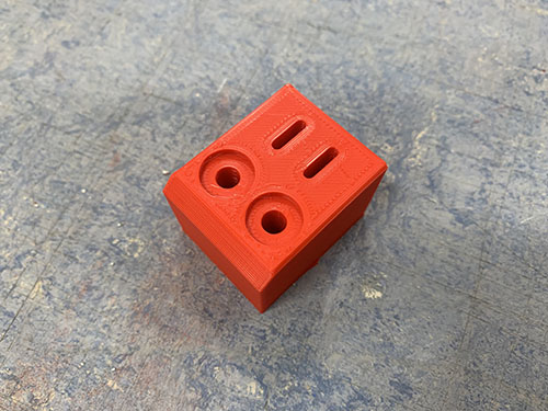
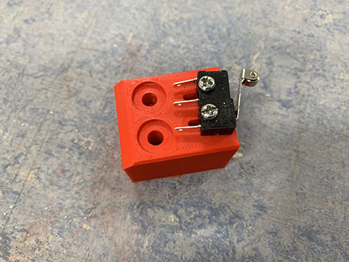
The end-stop mount was then pushed against the backside of the top bridge beam, which enabled the end-stop to trigger on the Z-axis stepper motor. The X-axis (carriage) was then moved to its maximum position and the end-stop mount was positioned in a way so that the end-stop triggered just before the X-axis reached its maximum position.
Please ignore the flexible conduit/hose in the next two images, it will be added in an upcoming step.
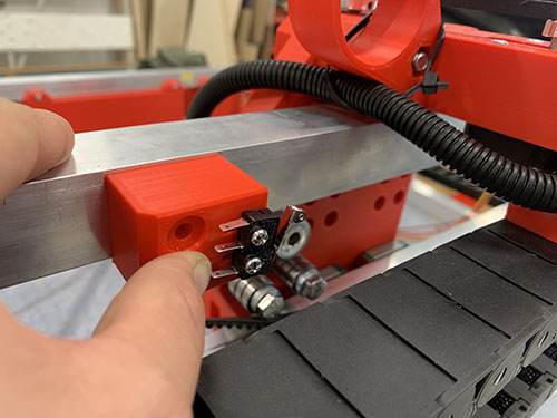
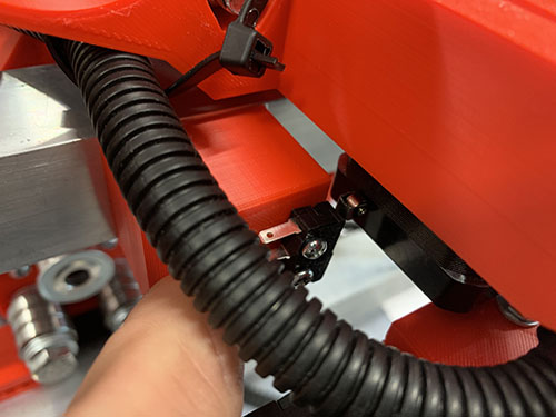
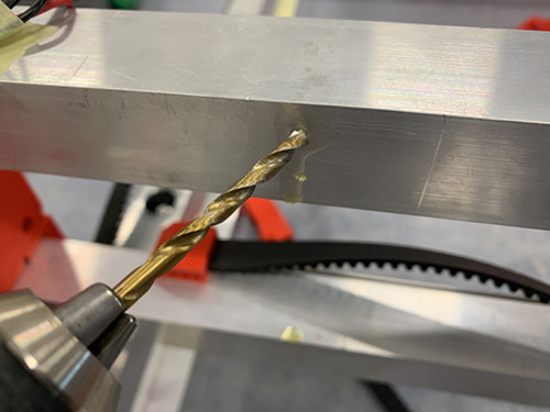
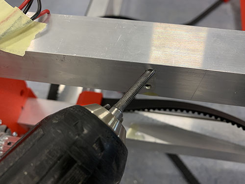
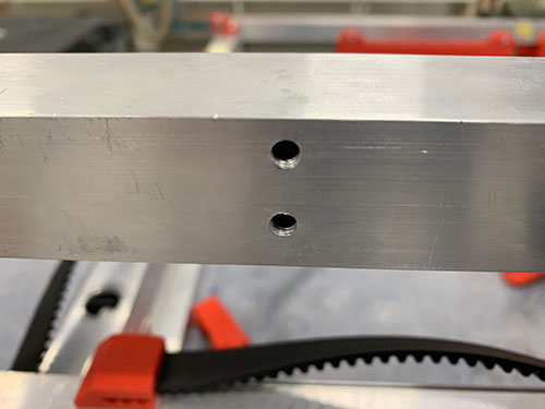
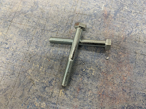
The end-stop mount was then clamped to the upper bridge beam and a small drill (-2 mm) was used to carefully make indentations at the center of the holes. The end-stop mount was then removed. Cutting fluid was applied and a 4 mm drill was used to drill the holes, followed by a M5 drill tap. The end-stop mount was then attached to the upper bridge beam using 2x 40 mm M5 screws (S13).
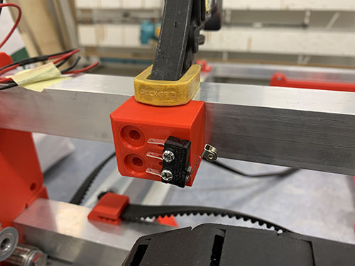
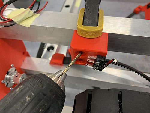
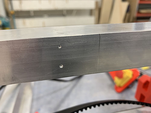
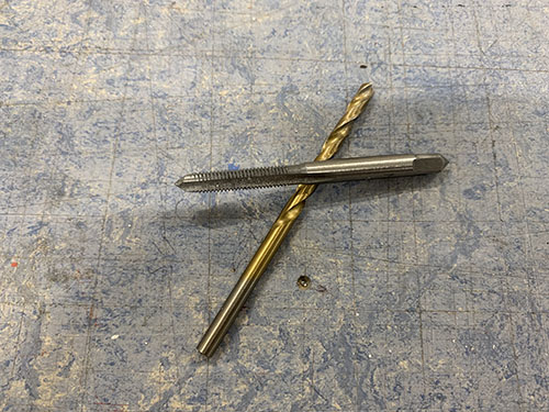
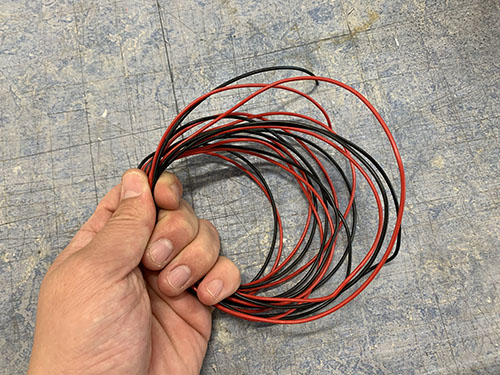
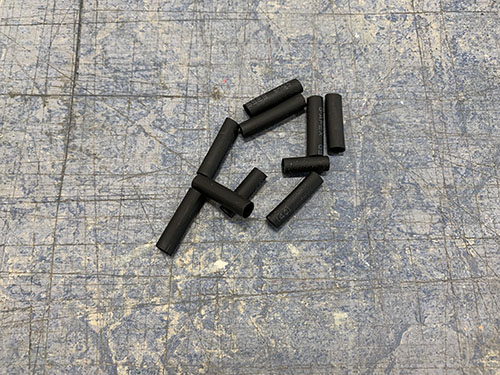
One black and one red 0.75 mm^2 wire (E03) were cut out at a length so that they reached from the X-axis max end-stop to the right side plate, through the top bridge beam and through the Y-axis cable chain to the front of the CNC machine. A handful of shrinking tubes (O24) were shrunk around the wires to keep them together.
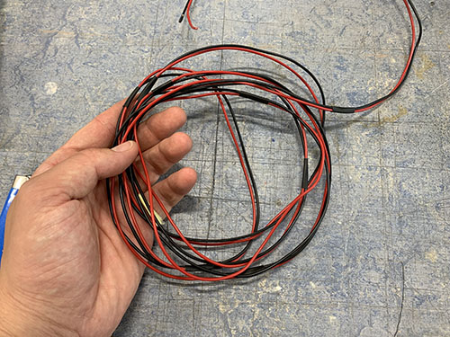
One end of the wires were taped together and inserted through the upper bridge beam to the side plate on the other side.
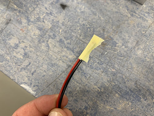
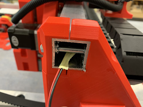
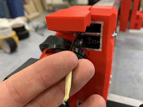
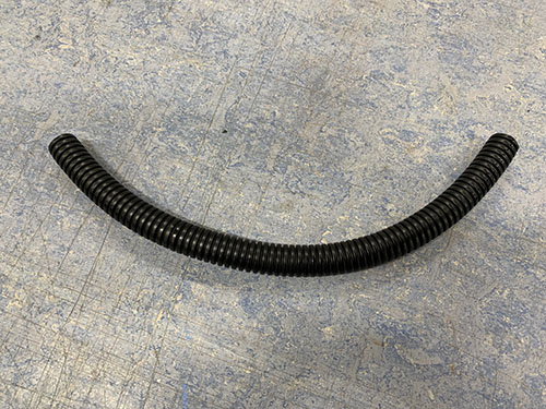
A flexible conduit/hose (O13) was then cut out and the other side of the cables were inserted through the conduit. The flexible conduit was then inserted ~50 mm into the upper bridge beam and the other side was attached to the outside of the upper bridge beam using cable ties (O11).
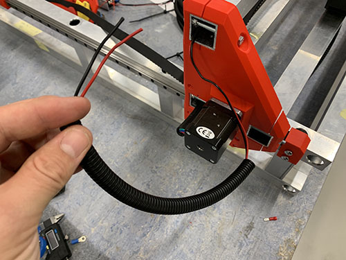
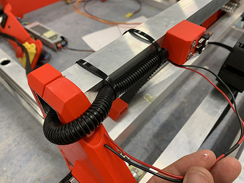
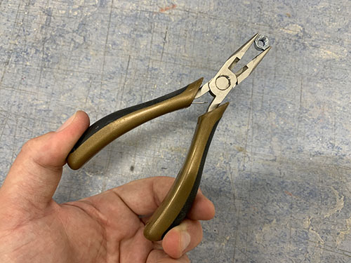
The end of the wires were stripped and twisted. Two 2.8 mm spade connectors (E25) were then attached to the stripped wires using a plier. The red wire was then attached to C (Common terminal) pinout on the end-stop and the black cable was connected to the NO (Normally Open) pinout.
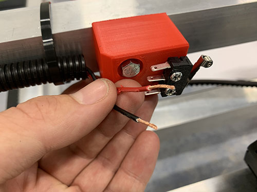
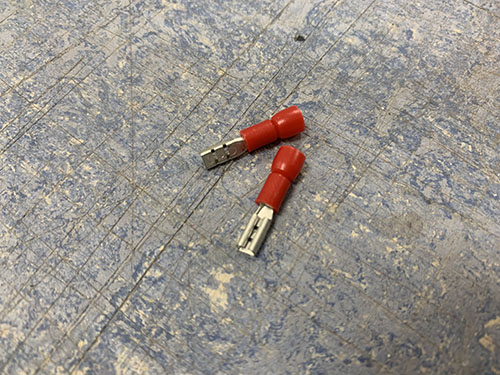
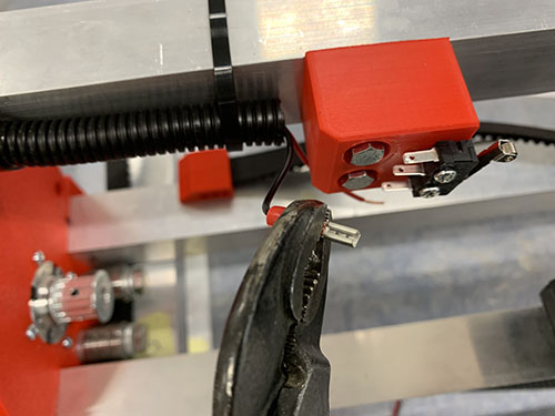
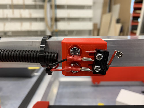
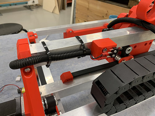
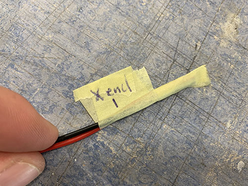
Finally, the open end of the wires were marked using tape (O23) and a penn, indicating which end-stop the cables belonged to. This is important as it will help a lot later on, when the end-stops are connected to the Arduino.
X-axis (min)
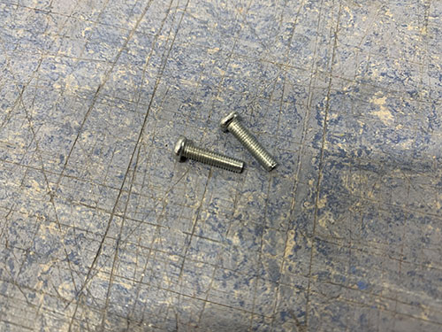
A microswitch (E21) was attached to the X-axis end-stop (-) mount (P08) using 2x 12mm M3 screws (S02).
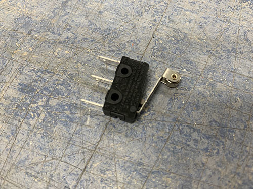
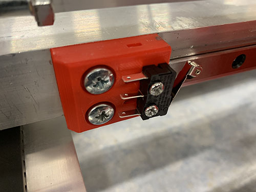
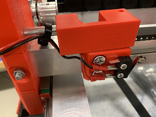
One black and one red 0.75 mm^2 wire (E03) were cut out at a length so that they reached from the X-axis end-stop (-), around the left side plate, through the Y-axis cable chain to the front of the CNC machine. A handful of shrinking tubes (O24) were shrunk around the wires to keep them together.
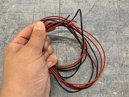
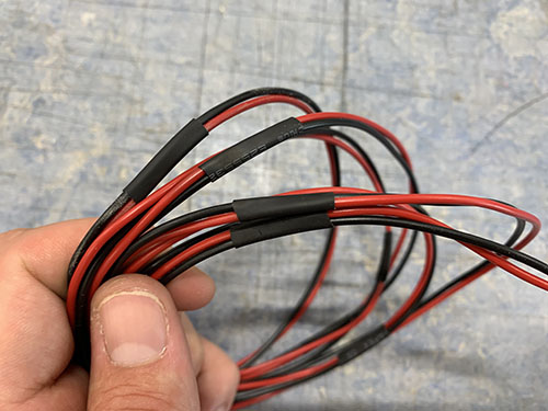
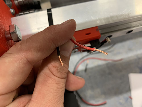
The end of the wires were stripped and twisted. Two 2.8 mm spade connectors (E25) were then attached to the stripped wires using a plier. The red wire was then attached to C (Common terminal) pinout on the end-stop and the black cable was connected to the NO (Normally Open) pinout.
The wires were initially strapped around the lower front bridge beam (seen in the first two images), but as it turned out it blocked the belt tensioner. So they were instead strapped around the M8 tensioner screw, using a cable tie (O11).
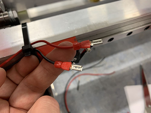
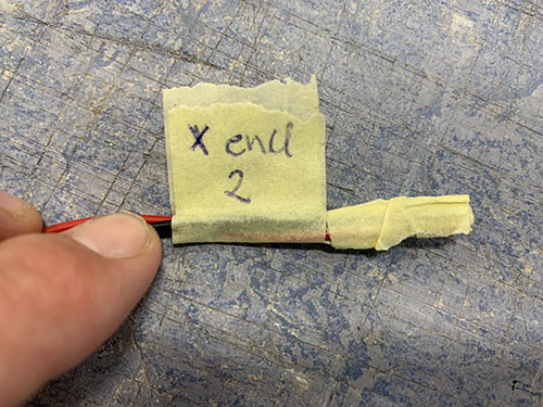
Finally, the open end of the wires were marked using tape and a penn, indicating which end-stop the cables belonged to.
Y-axis (max)
The tall Y-axis end-stop (+) mount (P09) was clamped to the inner side of the upper frame and a sharpie was used to indicate the center of the holes. Note that this end-stop mount can probably be redesigned to gain an extra ~10 mm of Y-axis movement, something I will probably do in the future.
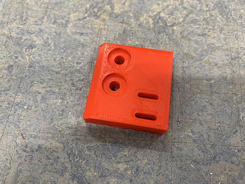
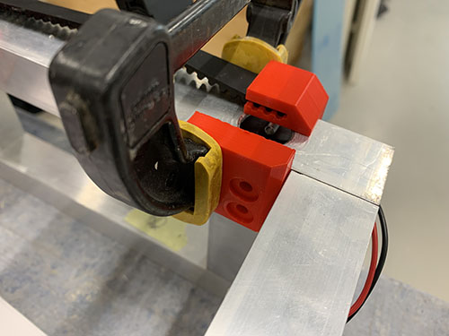
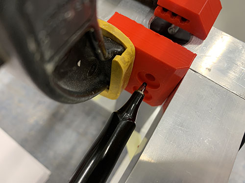
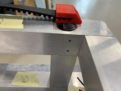
A bradawl and a hammer were then used to make indentations at the center of the holes. Cutting fluid was applied and a 4 mm drill was used to drill the holes, followed by a M5 drill tap. The end-stop mount was then attached to the inside of the upper frame using 2x 20 mm M5 screws (S12).
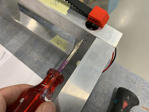
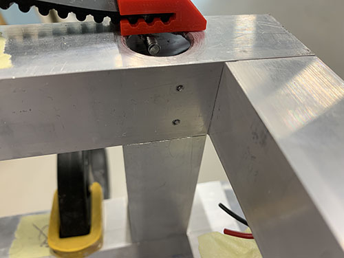
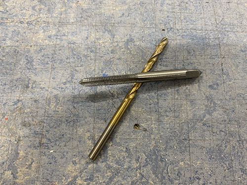
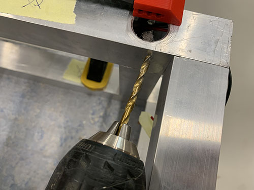
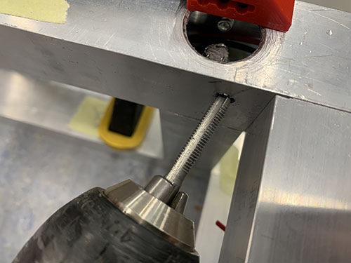
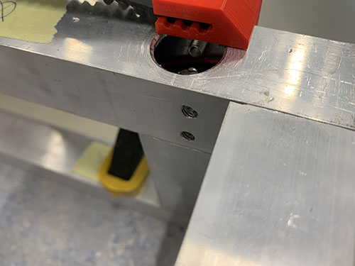
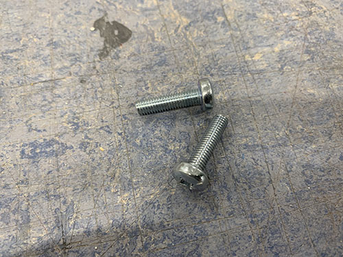
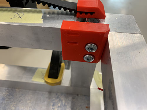
One black and one red 0.75 mm^2 wire (E03) were cut out at a length so that they reached from the Y-axis end-stop (+) and through the 900 mm aluminium profile of the upper frame to the front of the CNC machine.
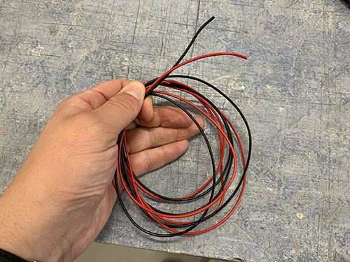
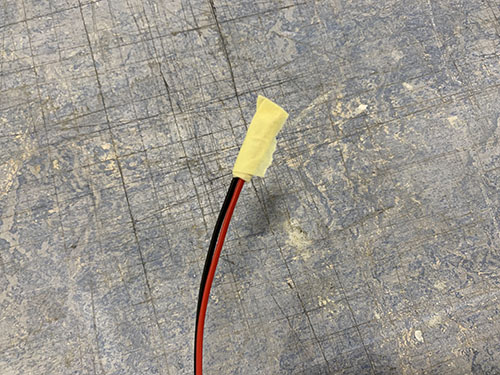
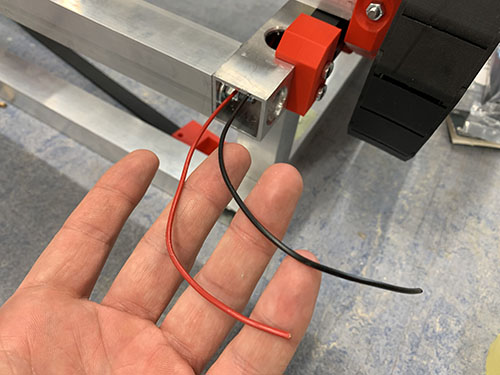
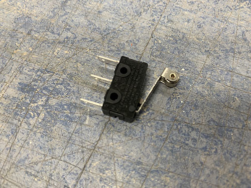
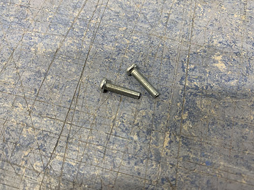
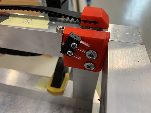
A microswitch (E21) was attached to the tall Y-axis end-stop (+) mount using 2x 12mm M3 screws (S02).
A flexible conduit/hose (O13) was then cut out and the wires were inserted through the conduit. The flexible conduit was then inserted ~50 mm into the 900 mm aluminium profile of the upper frame. The other side was bent around and attached to the outside of the upper frame using cable ties (O11).
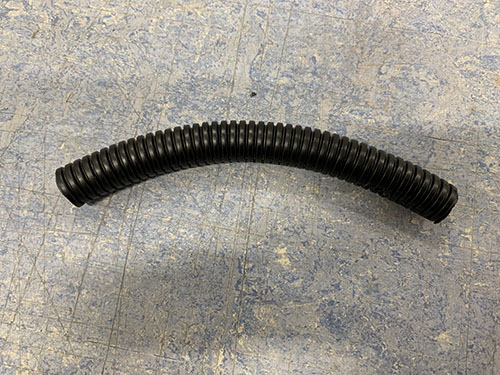
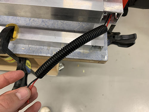
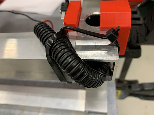
The end of the wires were stripped and twisted. Two 2.8 mm spade connectors (E25) were then attached to the stripped wires using a plier. The red wire was then attached to C (Common terminal) pinout on the end-stop and the black cable was connected to the NO (Normally Open) pinout.
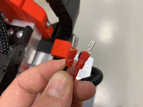
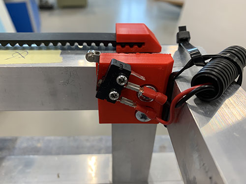
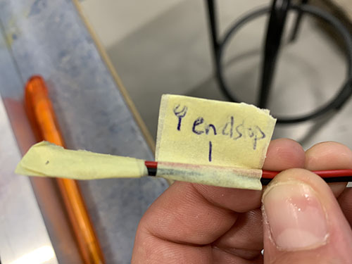
Finally, the open end of the wires were marked using tape and a penn, indicating which end-stop the cables belonged to.
Y-axis (min)
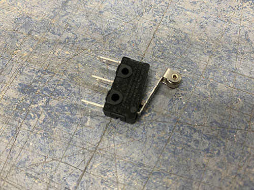
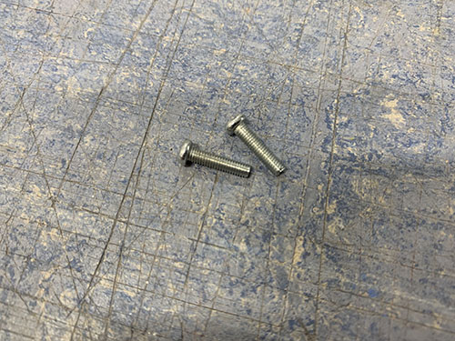
A microswitch (E21) was attached to the Y-axis end-stop (-) mount (P08) using 2x 12mm M3 screws (S02).
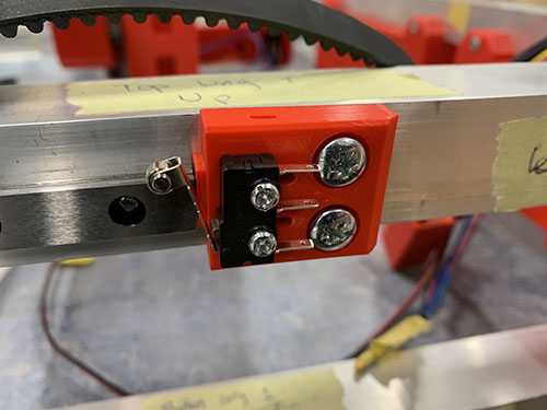
One black and one red 0.75 mm^2 wire (E03) were cut out at a length so that they reached from the Y-axis end-stop (-) and to the front of the CNC machine.
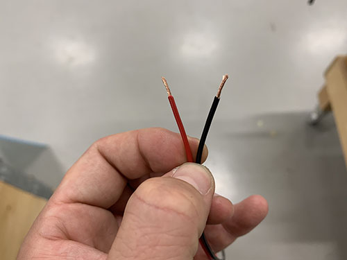
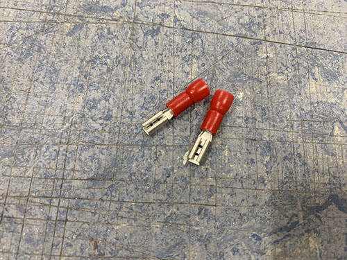
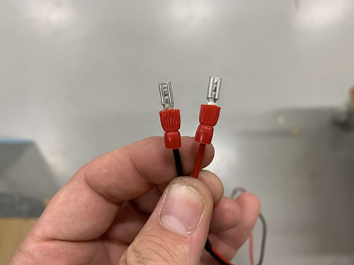
The end of the wires were stripped and twisted. Two 2.8 mm spade connectors (E25) were then attached to the stripped wires using a plier. The red wire were then attached to C (Common terminal) pinout on the end-stop and the black cable was connected to the NO (Normally Open) pinout.

A flexible conduit/hose (O13) was cut out and the wires were inserted through the conduit. The flexible conduit was attached to the outside of the upper frame using cable ties (O11).
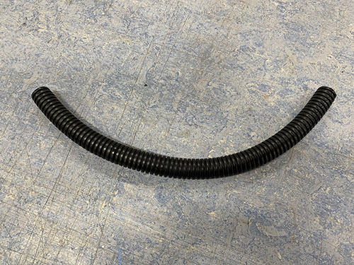
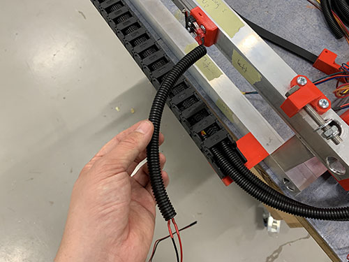
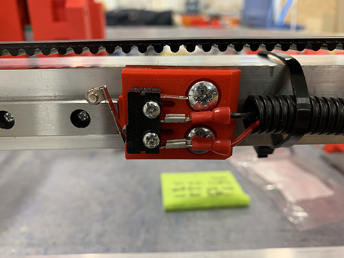
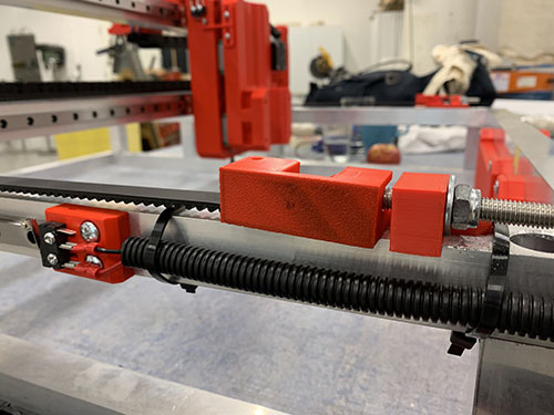
Finally, the open end of the wires were marked using tape and a penn, indicating which end-stop the cables belonged to.
Z-axis (max)
The main purpose of the Z-axis end-stop (+) is, apart from homing the machine, to limit the CNC machine from moving past what the length of the rails allow. As the MGN12H blocks contains a lot of small bearing balls, there's a high risk of them falling out if the blocks move past the rail.
To reduce the complexity and amount of wires, I chose not to include a Z-axis end-stop (-), as you are likely to mill straight through your waste board before there's a risk of moving past the Z-axis min limit. But if you want to add a Z-axis min end-stop, just repeat the process in this section with the new switch flipped around.
First, the vertical carriage slider was moved upwards to its maximum point, where the MGN12H blocks are just about to move past the limit of the rails. The Z-axis end-stop trigger (P39) was then pressed against the outside of the vertical carriage slider and a sharpie was used to mark the center of the holes.
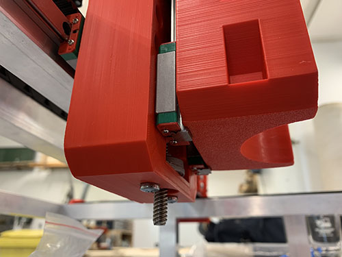
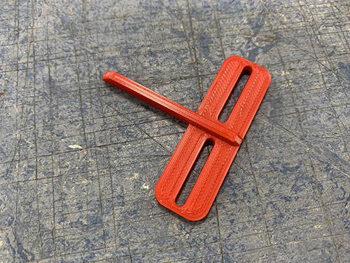
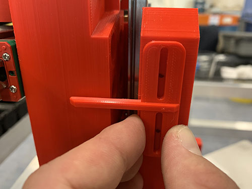
A 2.5 mm drill was used to drill the holes into the vertical carriage slider. A tip is to mark the drill depth needed using tape. The Z-axis end-stop trigger was then attached to the vertical carriage slider using 2x 12 mm M3 screws (S02).
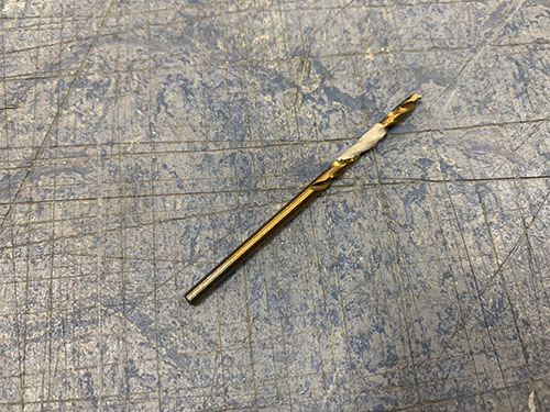
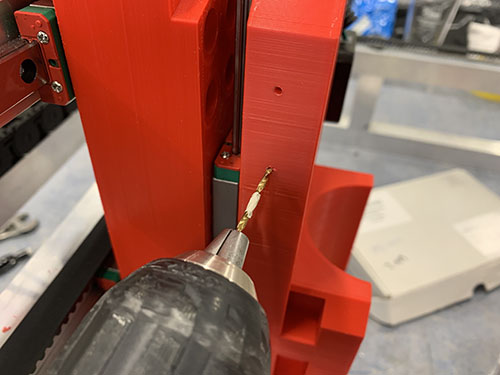
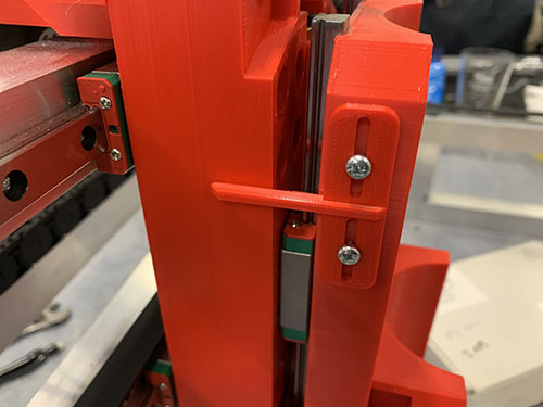
A microswitch (E21) was pressed against the carriage and positioned and aligned to be triggered by the maximum state of the Z-axis end-stop trigger.
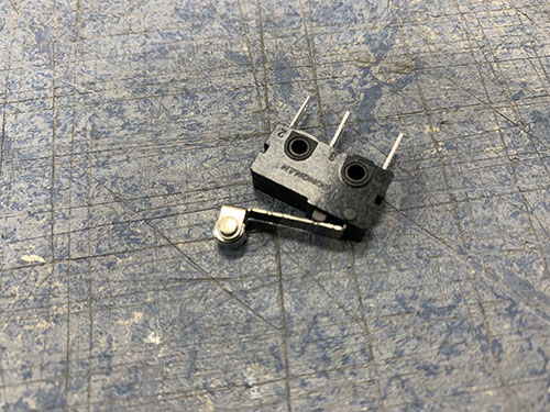
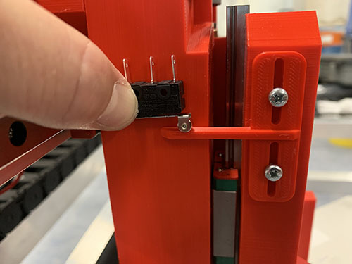
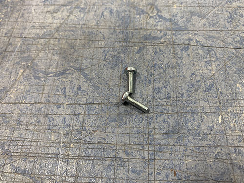
A 2.5 mm drill was used to drill the first hole into the carriage and the microswitch was attached to the carriage using 1x 12 mm M3 screw (S02). After the microswitch was locked into position, the second hole was drilled and the second 12 mm M3 screw (S02) was attached.
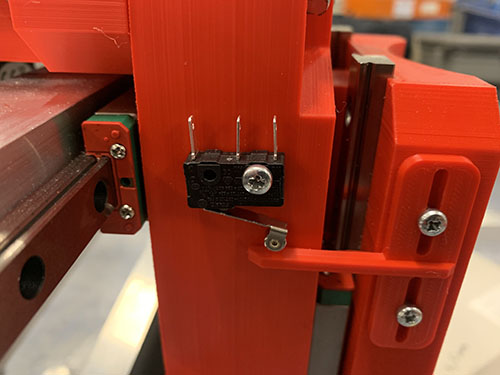
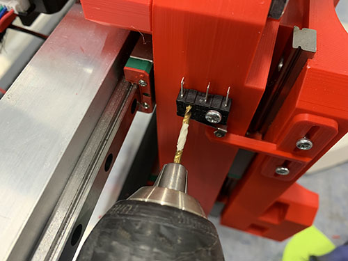
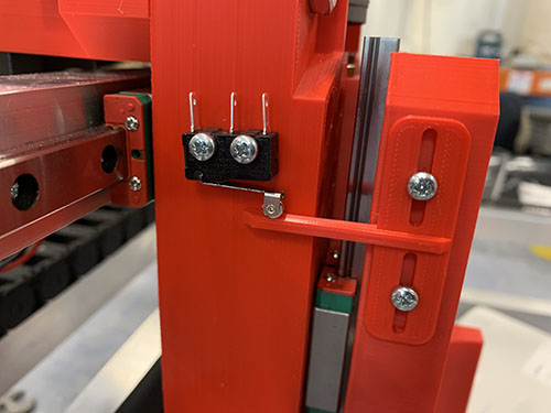
One black and one red 0.75 mm^2 wire (E03) were cut at a length so that they reached over the top bridge beam, through the X-axis cable chain and through the Y-axis cable chain to the front of the CNC machine. A handful of shrinking tubes (O24) were shrunk around the wires to keep them together.
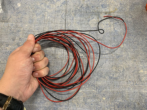
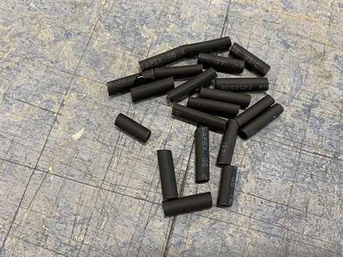
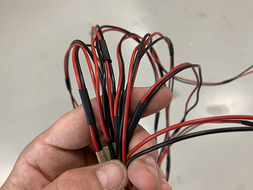
The end of the wires were stripped and twisted. Two 2.8 mm spade connectors (E25) were then attached to the stripped wires using a plier. The red wire was then attached to C (Common terminal) pinout on the end-stop and the black wire was connected to the NO (Normally Open) pinout.
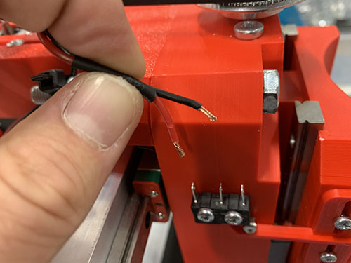
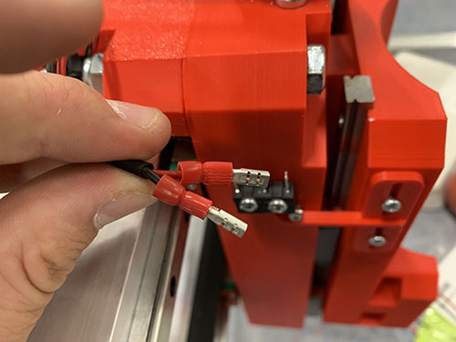
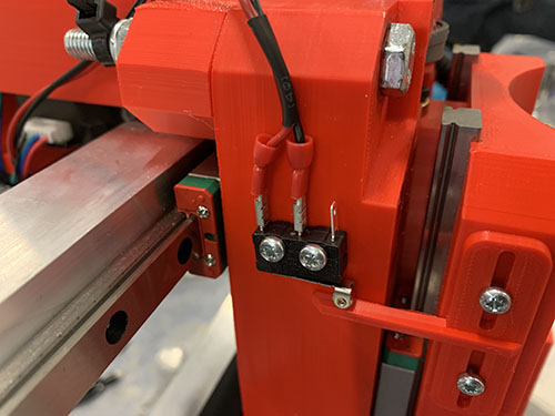
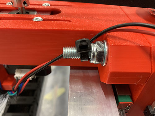
The wires were strapped around the M8 screw keeping the Z motor mount attached to the carriage, using a cable tie (O11).
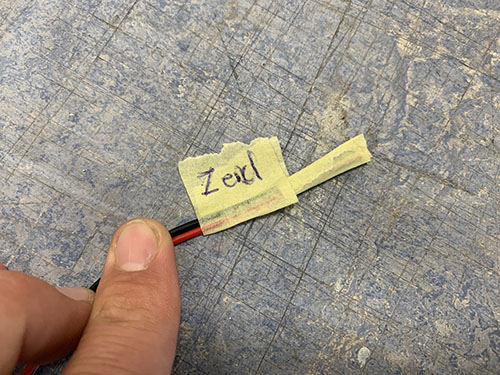
Finally, the open end of the wires were marked using tape and a penn, indicating which end-stop the cables belonged to.
Stepper motor and end-stop cable management
To keep a nice structure of all the wires, braided cable sleeves (O08) and flexible conduits/hoses (O13) were used.
Y-axis steppers and X-axis end-stops
First, the wires from the right-side Y-axis stepper motor were inserted into a small flexible conduit and pushed through the lower bridge beam closest to the carriage.
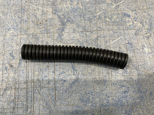
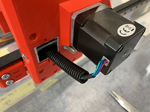
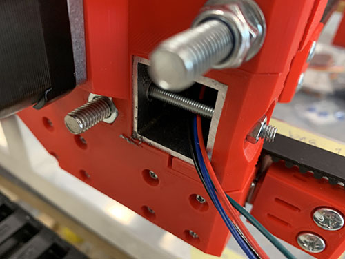
The wires from the two geared Y-axis stepper motors and the two X-axis end-stops were bundled together into the same cable sleeve.
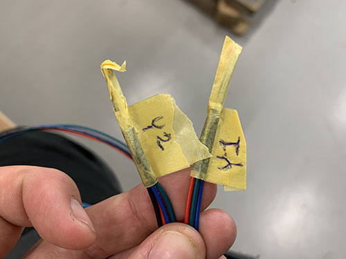
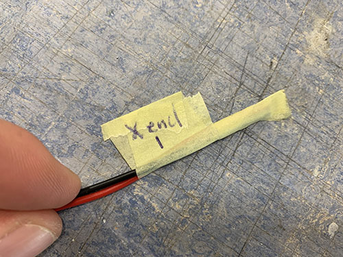
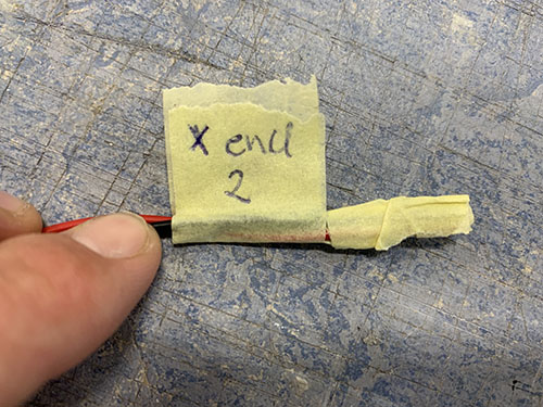
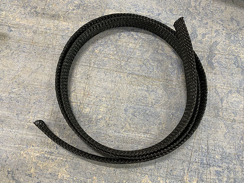
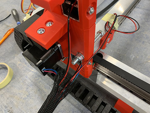
To simplify pushing the wires and the cable sleeve through the cable chain, the wires were taped together, leaving no loose ends to get stuck in the cable chain. This was needed as the wires were longer than the cable sleeve (to reach all the way to the small electronic box in the front of the CNC machine).
A cable tie (O11) was used to close the entrence of the cable sleeve.
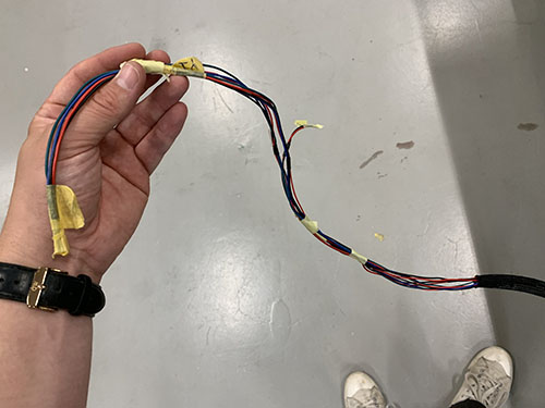
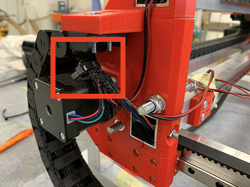
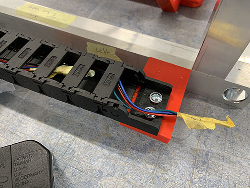
X-axis stepper, Z-axis stepper and Z-axis end-stop
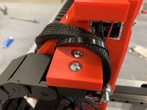
First, the wires from the X-axis stepper motor were inserted into a flexible conduit (O13). The conduit was then bent over the upper bridge beam, strapped to the vaccum mount and Z motor mount, and then pushed behind the Z-axis stepper motor.
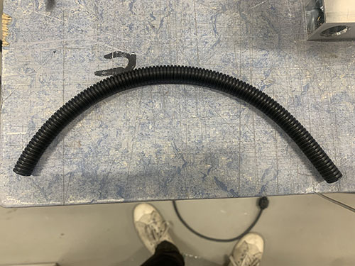
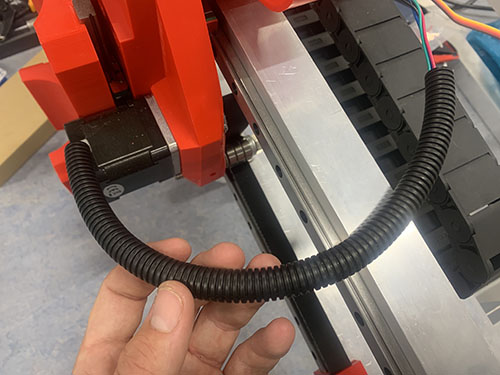
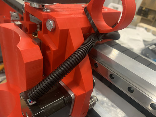
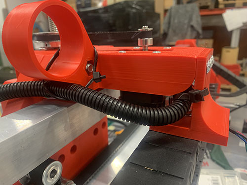
The wires from the X-axis stepper, Z-axis stepper and the Z-axis end-stop were bundled together into the same cable sleeve. The cable sleeve was cut at a length so that it reached through the X-axis cable chain, around the left side-plate and through the Y-axis cable chain.
To simplify pushing the wires through the cable chains, the wires were taped together, leaving no loose ends to get stuck in the cable chains. This was needed as the wires were longer than the cable sleeve (to reach all the way to the small electronic box in the front of the CNC machine).
A cable tie (O11) was used to close the entrence of the cable sock.
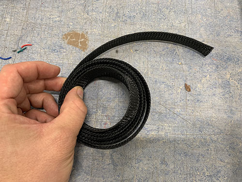
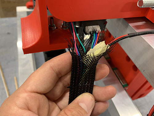
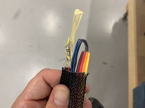
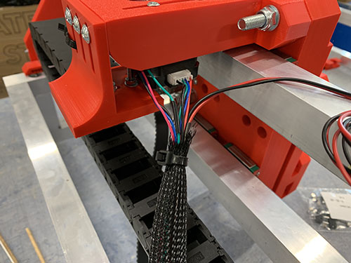
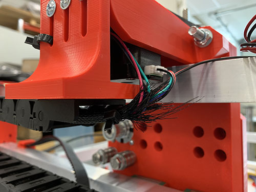
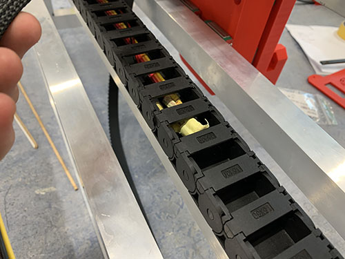
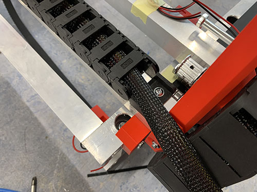
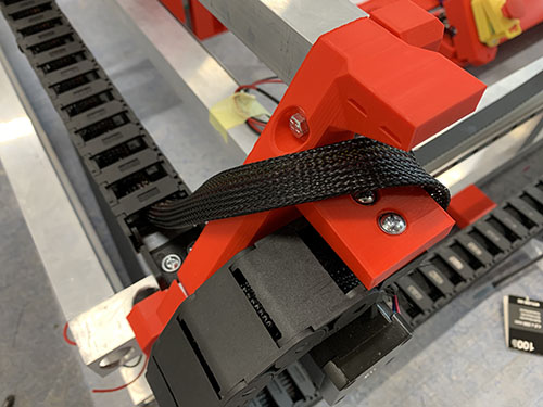
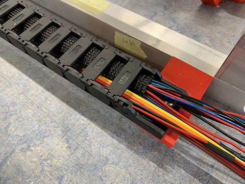
A cable tie (O11) was used to strap the cable sleeve to the left side-plate.
Router
Attach router to carriage
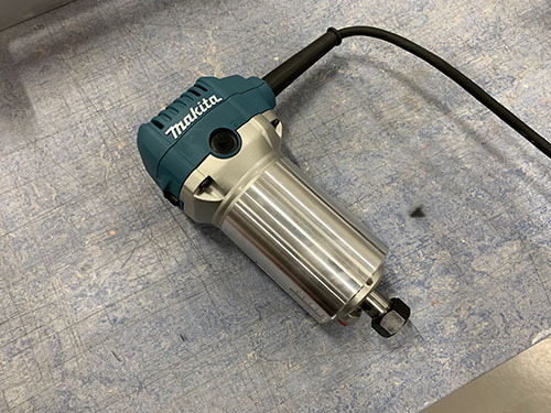
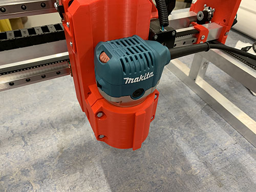
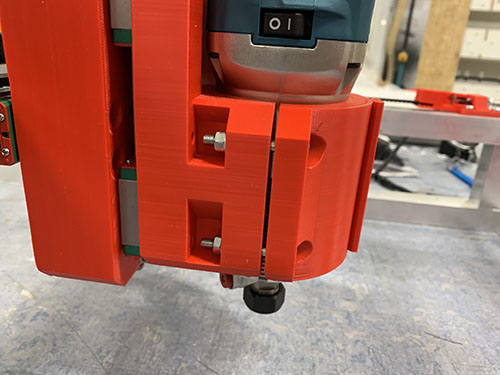
A Makita RT0700CJ (E20) trimming router was used as I was not able to get my hands on the Makita RT0700C that Ivan is using. To my knowledge, the RT0700CJ is just an upgraded European version of the RT0700C, with the same dimensions.
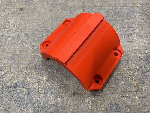
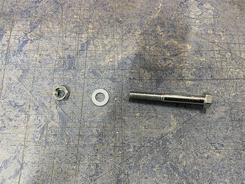
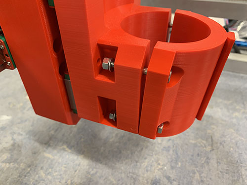
The trimming router was locked in place by using the router bracket (P24), 4x 40mm M5 screws (S13), 4x M5 nuts (N02) and 4x (10mm x 5mm x 1mm) washers (W01).
Router cable management
more like this
purecutcnc
PureCutCNC is a 2.5D CAD / CAM workspace for designing parts, defining machining operations, previewing toolpaths, and…