ikea-led-obegraensad
ESP32/Arduino hack for the ikea OBEGRÄNSAD led wall lamp
 ph1p
ph1pgit clone https://github.com/ph1p/ikea-led-obegraensad.gitph1p/ikea-led-obegraensadIKEA OBEGRÄNSAD Hack/Mod
Turn your OBEGRÄNSAD LED Wall Lamp into a live drawing canvas
⚠ Disclaimer: Use this code and instructions at your own risk! Improper use may damage the device. Contribute: Have suggestions or improvements? Feel free to submit a PR or open an issue. 😊
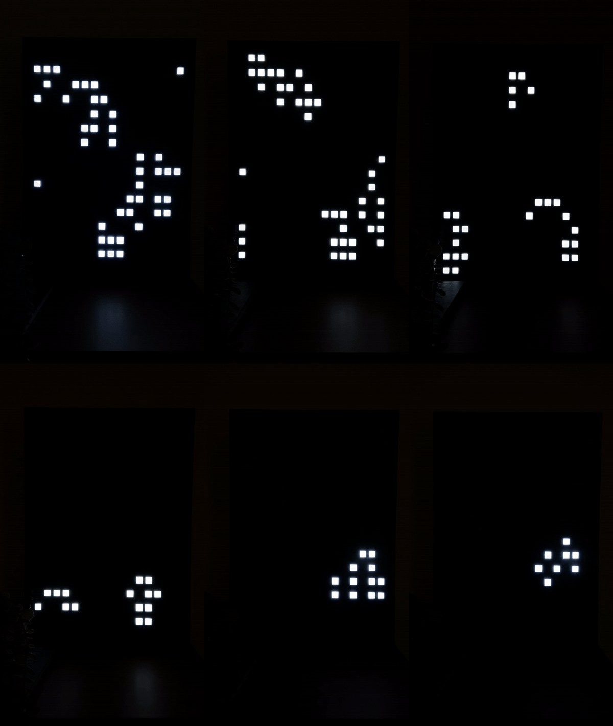
Table of Contents
- Features
- Quick Start
- Hardware Setup
- Software Setup
- OTA Updates
- HTTP API Reference
- DDP (Display Data Protocol)
- Home Assistant Integration
- Development
- Troubleshooting
Features
Click to expand feature list
General Features:
- Persist your drawing
- Rotate image
- Live Drawing
- OTA Update
- WiFi Control
- Web GUI
- Load an image
- Switch plugin by pressing the button
- Schedule Plugins to switch after "n" seconds
Available Plugins:
- Draw
- Game of Life
- Breakout
- Snake
- Stars
- Lines
- Circle
- Clock
- Big Clock
- Weather
- Rain
- Animation (with Animation Creator in Web UI)
- Firework
- DDP (Display Data Protocol)
- Pong Clock
Quick Start
Area.mp4
Control the lamp using the built-in web GUI. Find the device IP address via:
- Serial monitor output
- Router admin panel
Hardware Setup
This software is designed for ESP32 Dev Boards but can work with other Arduino boards (WiFi, OTA, and web server features will need to be removed for non-ESP boards).
Supported Boards:
- ESP32 Dev Board (recommended)
- TTGO LoRa32 V2.1 (T3_V1.6.1)
- ESP8266 (with limitations: per-pixel brightness only works when storage and global brightness are disabled)

Opening the Lamp
IKEA uses rivets instead of regular screws. To open:
- Insert a screwdriver between the rivets and back panel
- Carefully pry open with a second object
- Alternative: Drill out the rivets (cleaner but permanent)
Understanding the Panels

Inside you'll find 4 identical plates with 64 LEDs each (in 4 fields). Focus on the lowest plate:
- 6 connectors at the bottom edge (connection points for your board)
- Original microcontroller at the top (must be removed)

Pin Configuration
Connect the pins as shown below. Remember to configure them in include/constants.h according to your board.
| LCD | ESP32 | TTGO LoRa32 | NodeMCUv2 | Lolin D32 (Pro) | Xiao ESP32S3 |
|---|---|---|---|---|---|
| GND | GND | GND | GND | GND | GND |
| VCC | 5V | 5V | VIN | USB | VUSB |
| EN (PIN_ENABLE) | GPIO26 | IO22 | GPIO16 D0 | GPIO26 | D4 (GPIO5) |
| IN (PIN_DATA) | GPIO27 | IO23 | GPIO13 D7 | GPIO27 | D10 (MOSI) |
| CLK (PIN_CLOCK) | GPIO14 | IO02 | GPIO14 D5 | GPIO14 | D8 (SCK) |
| CLA (PIN_LATCH) | GPIO12 | IO15 | GPIO0 D3 | GPIO12 | D5 (GPIO6) |
| BUTTON one end | GPIO16 | IO21 | GPIO2 D4 | GPIO25 | D3 (GPIO4) |
| BUTTON other end | GND | GND | GND | GND | GND |

Alternate Button Wiring
You can use the original button wiring without adding external connections. See this issue by RBEGamer for details.
Software Setup
ESP32 Setup with VS Code and PlatformIO
-
Prerequisites
- Install Visual Studio Code
- Install the PlatformIO IDE extension from VS Code Extensions Marketplace
-
Clone the Project
git clone git@github.com:ph1p/ikea-led-obegraensad.git
cd ikea-led-obegraensad
code .
PlatformIO will automatically load dependencies.
-
Connect ESP32
- Connect your ESP32 via USB
- Verify the COM port in the PlatformIO Devices tab
-
Configure the Project
- Run
PlatformIO: Clean(Recycle bin icon in bottom toolbar) - Edit
include/secrets.hwith your WiFi credentials (ESP8266 only; ESP32 can use WiFi Manager) - Configure variables in
include/constants.h
- Run
-
Build the Project
- Click the
PlatformIO Buildicon (bottom toolbar) - If libraries are missing, install them via the PlatformIO Libraries tab
- Repeat
CleanandBuilduntil successful
- Click the
-
Upload to ESP32
- Click
PlatformIO Upload(bottom toolbar)
- Click
WiFi Configuration
ESP32 (WiFi Manager - Recommended):
This project uses tzapu's WiFiManager. After booting:
- Device attempts to connect to known access points
- If none available, creates network named
Ikea Display Setup WiFi - Connect to this network on any device
- Captive portal guides you through WiFi configuration
- Device reboots and connects to your network
*Network name can be changed via WIFI_MANAGER_SSID in include/constants.h.
ESP8266 (Manual Configuration):
For ESP8266, WiFi Manager is not available. Set WIFI_SSID and WIFI_PASSWORD in include/secrets.h.
OTA Updates
Over-The-Air (OTA) updates allow you to upload new firmware wirelessly without a USB connection. This is powered by ElegantOTA.
Configuration
Before using OTA, configure the following:
-
Set OTA Credentials in
include/secrets.h:#define OTA_USERNAME "admin" #define OTA_PASSWORD "your-password"
-
Configure Upload Settings in
platformio.ini(for theesp32devenvironment):extra_scripts = upload.py upload_protocol = custom custom_upload_url = http://192.168.178.50 # Your device IP custom_username = admin custom_password = your-password
Note: Replace 192.168.178.50 with your device's actual IP address.
Upload Methods
Method 1: Web Interface (Manual Upload)
- Navigate to
http://your-device-ip/updatein your browser - Login with your configured credentials (default:
admin/ikea-led-wall) - Select your firmware file (
.pio/build/esp32dev/firmware.bin) - Click "Update" and wait for completion
- Device will automatically reboot with new firmware
Method 2: PlatformIO (Automated Upload)
Upload directly from PlatformIO via the command line:
pio run -e esp32dev -t upload
Or use the PlatformIO Upload button in VS Code (bottom toolbar).
Requirements:
- Python packages:
requests_toolbeltandtqdm - Install if needed:
pip install requests_toolbelt tqdm
Visual Feedback
During OTA updates, the LED matrix provides visual feedback:
- "U" letter displayed: Update has started
- Serial output: Progress updates every second
- "R" letter displayed: Update completed (device will reboot)
Monitor the serial output for detailed progress:
OTA update started!
OTA Progress Current: 262144 bytes, Final: 1440655 bytes
OTA Progress Current: 524288 bytes, Final: 1440655 bytes
...
OTA update finished successfully!
Troubleshooting:
- Ensure device is connected to the same network
- Verify IP address in
platformio.inimatches device IP - Check credentials match in both
secrets.handplatformio.ini - For upload failures, try the web interface method first
HTTP API Reference
Base URL: http://your-server/api
Device Information
Get device info, current state, and available plugins
GET /api/info
Example:
curl http://your-server/api/info
Response:
{
  "rows": 16,
  "cols": 16,
  "status": "active",
  "plugin": 3,
  "rotation": 90,
  "brightness": 255,
  "scheduleActive": true,
  "schedule": [
    { "pluginId": 2, "duration": 60 },
    { "pluginId": 4, "duration": 120 }
  ],
  "plugins": [
    { "id": 1, "name": "Plugin One" },
    { "id": 2, "name": "Plugin Two" }
  ]
}
Plugin Control
Set active plugin by ID
PATCH /api/plugin?id={plugin_id}
Example:
curl -X PATCH "http://your-server/api/plugin?id=7"
Response:
{
  "status": "success",
  "message": "Plugin set successfully"
}
Error Response:
{
  "error": true,
  "errormessage": "Could not set plugin to id 7"
}
Display Control
Set Brightness
PATCH /api/brightness?value={0-255}
Example:
curl -X PATCH "http://your-server/api/brightness?value=100"
Response:
{
  "status": "success",
  "message": "Brightness set successfully"
}
Get Display Data
Retrieve current display data as a byte-array. Each byte represents pixel brightness (0-255). Global brightness is applied after these values.
GET /api/data
Example:
curl http://your-server/api/data
Response:
[255, 255, 255, 0, 128, 255, 255, 0, ...]
Message Display
Display a Message
Display scrolling text and/or graphs on the LED matrix.
GET /api/message
Parameters:
text(optional): Text message to displaygraph(optional): Comma-separated integers (0-15) representing a graphminy(optional): Graph lower bound (default: 0)maxy(optional): Graph upper bound (default: 15)repeat(optional): Repetition count (default: 1, use-1for infinite)id(optional): Unique identifier for the messagedelay(optional): Scroll delay in ms (default: 50)
Example:
curl "http://your-server/api/message?text=Hello&graph=8,5,2,1,0,0,1,4,7,10,13,14,15,15,14,11&repeat=3&id=1&delay=60"
Response:
{
  "status": "success",
  "message": "Message received"
}
Remove a Message
GET /api/removemessage?id={message_id}
Example:
curl "http://your-server/api/removemessage?id=1"
Plugin Scheduler
Automatically switch between plugins on a schedule.
Set Schedule
POST /api/schedule
Example:
curl -X POST http://your-server/api/schedule -d 'schedule=[{"pluginId":10,"duration":2},{"pluginId":8,"duration":5}]'
Start Schedule
GET /api/schedule/start
Stop Schedule
GET /api/schedule/stop
Clear Schedule
GET /api/schedule/clear
Storage Management
Clear Storage
GET /api/clearstorage
Example:
curl http://your-server/api/clearstorage
DDP (Display Data Protocol)
DDP enables real-time LED matrix control via UDP packets. External applications can send pixel data directly over the network.
Python project setup with Poetry
Please install Poetry for an easy way to setup the Python environment.
To install all required dependencies and create a virtual environment run:
poetry install
VS Code should detect the venv automatically and prompt you to activate it. Once that's done you can use the python command as usual. Alternatively use the poetry run command to make sure the python from the virtual environment is executed, e.g.:
poetry run python ddp.py clear
Quick Start
-
Enable DDP Plugin
curl -X PATCH "http://your-server/api/plugin?id=17"
-
Send Pixels
python3 ddp.py --ip 192.168.178.50 --fill 128
Using ddp.py
The included Python script (ddp.py) simplifies DDP packet creation. It offers a rudimentary command line interface to control display content.
Clear all pixels:
python3 ddp.py clear --ip 192.168.178.50
Fill display with brightness value:
python3 ddp.py fill 128 --ip 192.168.178.50
Set individual pixels (X, Y, brightness):
python3 ddp.py pixels --ip 192.168.178.50 -p 0 0 255 -p 15 15 128
Subcommands:
clear: Clear all pixelsfill BRIGHTNESS: Fill with brightness (0-255)pixels -p X Y BRIGHTNESS: Set pixel (-p can be used multiple times)
Options (for all subcommands):
--ip: Display IP address (default: 192.168.178.50)--port: UDP port (default: 4048)-v, --verbose: Write more information to output-d, --debug: Write even more information to output
Legacy options (still available for compatibility):
--clear: Clear all pixels--fill BRIGHTNESS: Fill with brightness (0-255)--pixel X Y BRIGHTNESS: Set pixel (can be used multiple times)
Coordinates:
- Matrix: 16×16 pixels
- X: 0-15 (left to right)
- Y: 0-15 (top to bottom)
- Brightness: 0-255
Protocol Specification
Packet Structure:
[Header: 10 bytes][RGB Data: 768 bytes for 16×16]
Header (10 bytes):
- Byte 0:
0x41(Version 1) - Byte 1:
0x00(Flags) - Bytes 2-9:
0x00(Reserved)
RGB Data:
- 3 bytes per pixel (R, G, B)
- Total: 16 × 16 × 3 = 768 bytes
- Order: Row-major (left to right, top to bottom)
- Brightness calculated as:
(R + G + B) / 3
Single Pixel Mode: Send only 3 RGB bytes (total: 13 bytes) to apply the same color to all pixels.
Example (Python):
import socket

# Create DDP packet
header = bytearray([0x41, 0x00, 0x00, 0x00, 0x00, 0x00, 0x00, 0x00, 0x00, 0x00])
pixels = bytearray([128, 128, 128] * 256)  # Fill with mid-brightness
packet = header + pixels

# Send packet
sock = socket.socket(socket.AF_INET, socket.SOCK_DGRAM)
sock.sendto(packet, ("192.168.178.50", 4048))
sock.close()
Home Assistant Integration
HACS Integration (Recommended)
Use this Home Assistant Integration for easy setup with seamless integration and instant updates via websockets.
HTTP API Integration
Example automation to adjust brightness based on sun position:
configuration.yaml:
rest_command:
  obegraensad_brightness_high:
    url: 'http://your-server/api/brightness/'
    method: PATCH
    content_type: 'application/x-www-form-urlencoded'
    payload: 'value=100'
  obegraensad_brightness_low:
    url: 'http://your-server/api/brightness/'
    method: PATCH
    content_type: 'application/x-www-form-urlencoded'
    payload: 'value=1'
Automation (Settings → Automations → Edit in YAML):
alias: Obegraensad low brightness
description: ''
triggers:
  - trigger: sun
    event: sunset
    offset: 0
conditions: []
actions:
  - action: rest_command.obegraensad_brightness_low
    data: {}
mode: single
Create a second automation or condition to call rest_command.obegraensad_brightness_high at sunrise.
Development
Arduino/C++ Development
Structure:
src/- Arduino codeplatformio.ini- Build configuration- See OTA Updates section for wireless firmware upload configuration
Frontend Development
Structure:
frontend/- Web UI code built with solidjsfrontend/src/- Source filesfrontend/dist/- Built files (generated)
Prerequisites:
This project uses pnpm as the package manager. pnpm is an alternative to npm.
Install pnpm:
# Using npm
npm install -g pnpm

# Using Homebrew (macOS)
brew install pnpm

# Using Corepack (Node.js 16.13+)
corepack enable
corepack prepare pnpm@latest --activate
Setup:
cd frontend
pnpm install
Configuration:
Create a .env file in the frontend/ directory and set your device IP:
VITE_DEVICE_IP=192.168.178.50
This allows the development server to proxy API requests to your device during development.
Commands:
pnpm dev- Start development server with hot reload (usually athttp://localhost:5173)pnpm build- Build optimized production bundle and generatewebgui.cppfor ESP32pnpm preview- Preview production build locallypnpm lint- Run linter to check code qualitypnpm format- Format code with Prettier
Development Workflow:
- Start the development server:
pnpm dev - Make changes to files in
frontend/src/ - Changes will hot-reload in your browser
- Test your changes against a running device
- When ready, run
pnpm buildto generate the embedded web UI - The build process creates
src/webgui.cppwhich is compiled into the firmware
Docker Build:
If you prefer using Docker instead of installing Node.js and pnpm locally:
docker compose run node
Code Quality
Pre-commit Hooks:
# Install pre-commit
pip install pre-commit

# Activate hooks
pre-commit install
Plugin Development
1. Create Plugin Files
plugins/MyPlugin.h:
#pragma once

#include "PluginManager.h"

class MyPlugin : public Plugin {
public:
    MyPlugin();
    ~MyPlugin() override;

    void setup() override;
    void loop() override;
    const char* getName() const override;

    void teardown() override; // optional
    void websocketHook(JsonDocument &request) override; // optional
};
plugins/MyPlugin.cpp:
#include "plugins/MyPlugin.h"

MyPlugin::MyPlugin() {
    // Constructor logic, if needed
}

void MyPlugin::setup() {
    // Setup logic for your plugin
}

void MyPlugin::loop() {
    // Loop logic for your plugin
}

const char* MyPlugin::getName() const {
    return "MyPlugin"; // name in GUI
}

void MyPlugin::teardown() {
    // code if plugin gets deactivated
}

void MyPlugin::websocketHook(JsonDocument &request) {
    // handle websocket requests
}
2. Register Plugin in main.cpp
#include "plugins/MyPlugin.h"

pluginManager.addPlugin(new MyPlugin());
Troubleshooting
Flickering Panel
- Verify all soldering points, especially VCC
- Ensure adequate power supply to the board
- Check for loose connections
- Try to connect the power supply directly to the microcontroller board
Microcontroller is stuck in boot loop / flickering panel / black panel
- Break the 5V connection between the matrix display and the microcontroller board (cut cable between controller and VCC and insulate ends with tape)
- Use separate USB power cables for the microcontroller and the matrix display (e.g. by using a power supply with 2x5V output of 10W each)
- Reason: When voltage drops too low on the microcontroller board output pins might not reach 3.3V, since the matrix display is actually expecting a 0V-5V signal the resulting output voltage of the microcontroller might be lower than the threshold of the matrix display resulting in flickering / completely black matrix displays. Additionally must power supplies only deliver 10W per port which is not always sufficient to power microcontroller and matrix displays (especially at brightness 100% and more than half the pixels being lit)
- Has the additional advantage that you can upload firmware without dissassembly of the backpanel if you cannot use OTA updates
more like this