esphome-soyosource-gtn-virtual-meter
ESPHome component to simulate the current clamp to control the Soyosource GTN1200 limiter
 syssi
syssigit clone https://github.com/syssi/esphome-soyosource-gtn-virtual-meter.gitsyssi/esphome-soyosource-gtn-virtual-meteresphome-soyosource-gtn-virtual-meter

ESPHome component to simulate the current clamp to control the Soyosource GTN1200 limiter
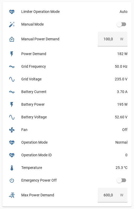
Supported devices
- GTN-1000LIM24, GTN-1000LIM36, GTN-1000LIM48, GTN-1000LIM72, GTN-1000LIM96
- GTN-1200LIM48, GTN-1200LIM72, GTN-1200LIM96
- GTN-1000LIM24W, GTN-1000LIM36W, GTN-1000LIM48W, GTN-1000LIM72W, GTN-1000LIM96W
- GTN-1200LIM48W, GTN-1200LIM72W, GTN-1200LIM96W
- GTN-1500LIM24W, GTN-2000LIM48W
It looks like there is no GTW (waterproof) version of the device with limiter / RS485 support.
Supported setups
| Configuration example | Description |
|---|---|
| esp32-example.yaml | Monitor1 the inverter and control the power output on demand both via RS485 using a ESP32 |
| esp8266-example.yaml | Monitor1 the inverter and control the power output on demand both via RS485 using a ESP8266 |
| esp32-limiter-example.yaml | Control the power output only on demand via RS485 using a ESP32 |
| esp8266-limiter-example.yaml | Control the power output only on demand via RS485 using a ESP8266 |
| esp8266-display-display-version-example.yaml | Monitor and control the inverter (Display version) using the internal display port |
| esp8266-display-display-version-limiter-example.yaml | Monitor and control the inverter (Display version) using the internal display port and control the power output on demand via RS485 |
| esp8266-display-wifi-version-example.yaml | Monitor and control the inverter (WiFi version) using the display port |
| esp8266-display-wifi-version-limiter-example.yaml | Monitor and control the inverter (WiFi version) using the display port and control the power output on demand via RS485 |
| esp8266-wifi-dongle-example.yaml | Monitor and control the inverter using the OEM WiFi dongle with a custom firmware |
| esp8266-wifi-dongle-example-web-only.yaml | Monitor and control the inverter using the OEM WiFi dongle with a custom firmware providing a nice web interface |
| esp8266-wifi-dongle-limiter-example.yaml | Monitor and control the inverter using the OEM WiFi dongle and control the power output on demand via RS485 |
| esp32-multiple-uarts-example.yaml | Monitor1 multiple inverters and control the power output on demand both via RS485 |
Requirements
- ESPHome 2024.6.0 or higher.
- RS485-to-TTL module (
HW-0519f.e.) - Generic ESP32 or ESP8266 board
- Required Soyosource inverter settings
- Battery CP Grid
N - Bat CP Mode Power
Upper power limit - Bat AutoLimit Grid
Y
- Battery CP Grid
Schematics
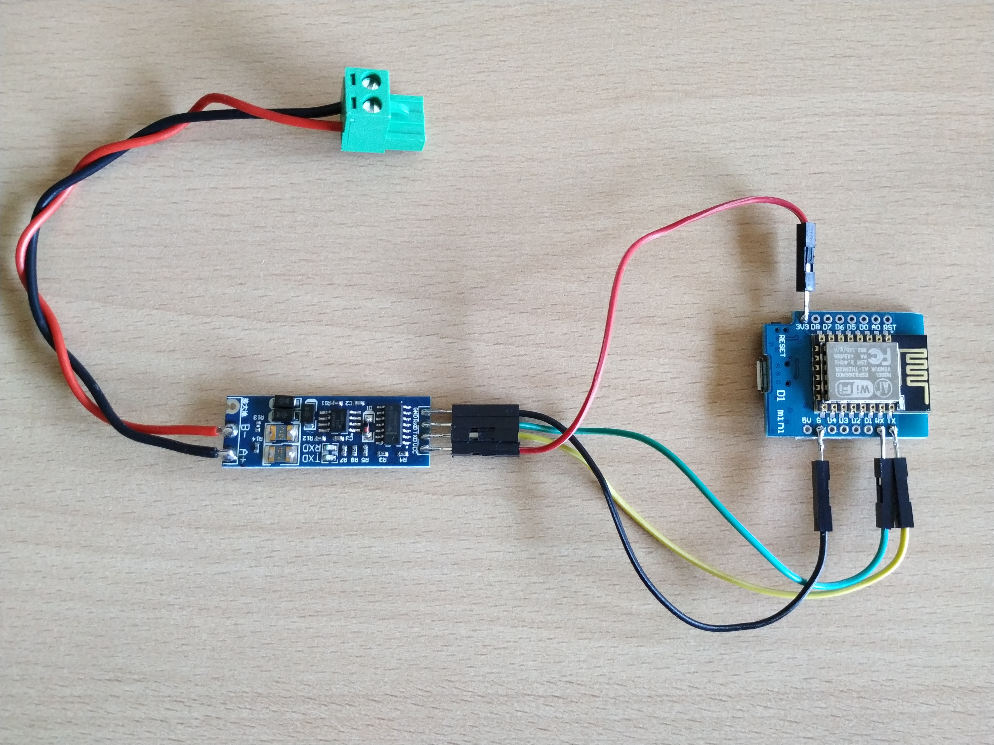
               RS485                      UART
┌─────────┐              ┌──────────┐                ┌─────────┐
│         │              │          │<----- RX ----->│         │
│         │<-----B- ---->│  RS485   │<----- TX ----->│ ESP32/  │
│ GTN1200 │<---- A+ ---->│  to TTL  │<----- GND ---->│ ESP8266 │
│         │<--- GND ---->│  module  │<-- 3.3 VCC --->│         │<-- VCC
│         │              │          │                │         │<-- GND
└─────────┘              └──────────┘                └─────────┘
Please make sure to power the RS485 module with 3.3V because it affects the TTL (transistor-transistor logic) voltage between RS485 module and ESP.
Installation
You can install this component with ESPHome external components feature like this:
external_components:
  - source: github://syssi/esphome-soyosource-gtn-virtual-meter@main
or just use the esp32-example.yaml / esp8266-example.yaml as proof of concept:
# Install esphome
pip3 install esphome

# Clone this external component
git clone https://github.com/syssi/esphome-soyosource-gtn-virtual-meter.git
cd esphome-soyosource-gtn-virtual-meter

# Create a secrets.yaml containing some setup specific secrets
cat > secrets.yaml <<EOF
wifi_ssid: MY_WIFI_SSID
wifi_password: MY_WIFI_PASSWORD

mqtt_host: MY_MQTT_HOST
mqtt_username: MY_MQTT_USERNAME
mqtt_password: MY_MQTT_PASSWORD
EOF

# Validate the configuration, create a binary, upload it, and start logs
# If you use a esp8266 run the esp8266-examle.yaml
esphome run esp32-example.yaml
For a more advanced setup take a look at the esp32-multiple-uarts-example.yaml.
Known issues
None.
Debugging
If this component doesn't work out of the box for your device please update your configuration to enable the debug output of the UART component and increase the log level to the see outgoing and incoming serial traffic:
logger:
  level: DEBUG
  logs:
    api.service: WARN
    ota: WARN
    sensor: DEBUG

uart:
  baud_rate: 4800
  tx_pin: ${tx_pin}
  rx_pin: ${rx_pin}
  debug:
    direction: BOTH
References
- https://github.com/drcross/virtual-meter
- https://www.photovoltaikforum.com/thread/148552-g%C3%BCnstiger-1200w-grid-tie-inverter-mit-limiter-sensor-von-soyo-source-%C3%A4hnlich-gti/?pageNo=4
- https://secondlifestorage.com/index.php?threads/limiter-inverter-with-rs485-load-setting.7631/
- https://github.com/PepeTheFroggie/Soyosource-GridTie-inverter-24V-LCD-replacement
Footnotes
-
Some devices doesn't respond to the status request (
0x24 0x00 0x00 0x00 0x00 0x00 0x00 0x00) via RS485. The reason is unknown. This has no effect on the limiter feature. The inverter processes the power demand requests silently. There is a new hardware version since 2022 (purple mainboard / fw versionSTC8-2022-218) which probably doesn't respond to requests anymore. The 2021 version (blue mainboard & green mainboard, fw version2021-301) responds for some people and for some not. (#48) ↩ ↩2 ↩3
more like this
markItDown
📱 A React app to preview and edit Markdown✍. You can also export it as HTML.